
Datasheet


TEF6901A_3 © NXP B.V. 2008. All rights reserved.
Product data sheet Rev. 03 — 20 March 2008 96 of 107
NXP Semiconductors
TEF6901A
Integrated car radio
[1] The equivalent level voltage is that value of the level voltage (on pin LEVEL) which results in the same weak signal control effect (for
instance HCC roll-off) as the output value of the specified detector (USN, WAM and multipath).
[2] Crosstalk between bus inputs and signal outputs:
[3] The input gain setting ING and the volume setting VOL define the overall volume. The overall range is limited to −83 dB to +28 dB. For
values > +28 dB the actual value is +28 dB. For overall values < −83 dB the actual value is mute.
[4] The maximum bass gain including BASS setting is +20 dB.
13. I
2
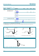
C-bus characteristics
The maximum I
2
C-bus communication speed is 400 kbit/s. SDA and SCL HIGH and LOW
internal thresholds are specified according to an I
2
C-bus voltage range from 2.5 V to 3.3 V
including I
2
C-bus voltage tolerances of 10 %. The bus interface tolerates also SDA and
SCL signals from a 5 V bus. Restrictions for V
IL
in a 5 V application can be derived from
Table 112.
EQ
bow
equalizer bowing f
audio
= 1 kHz;
V
i
= 500 mV (RMS);
G
bass
= +12 dB; f
bass
=60Hz;
G
treble
= +12 dB;
f
cut(treble)
=15kHz
- 1.8 - dB
Fader
G
fader
fader gain control see Table 91
maximum setting - 0 - dB
minimum setting - −64 - dB
output mute - - −80 dB
G
step(fader)
step resolution gain - 1 - dB
∆G
step(fader)
fader step error - - 1 dB
α
mute
audio mute volume control: mute and
output muted (bits MULF,
MURF, MULR and MURR)
80 90 - dB
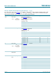
Table 111. Dynamic characteristics of the sound processor
…continued
V
CC
= 8.5 V; T
amb
=25
°
C; see Figure 43; all AC values are given in RMS; treble: 10 kHz filter frequency; treble = 0 dB;
bass: 60 Hz filter frequency; bass = 0 dB; f
audio
= 1 kHz; G
vol
= 0 dB; G
fader
= 0 dB; loudness off; standard output gain
(byte OUTPUT; bit OUTA = 0); R
L
= 10 k
Ω
; C
L
= 1 nF; unless otherwise specified.
Symbol Parameter Conditions Min Typ Max Unit
α
ct
20log
V
bus(p-p)
V
o(rms)
--------------------
=
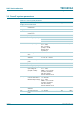
Table 112. I
2
C-bus parameters
Symbol Parameter Conditions Min Typ Max Unit
V
IL
LOW-level input voltage - - 1.09 V
V
IH
HIGH-level input voltage 1.56 - - V
C
SDA
capacitance of SDA pin - 4 6 pF
C
SCL
capacitance of SCL pin - 3 5 pF