
Datasheet


TEF6901A_3 © NXP B.V. 2008. All rights reserved.
Product data sheet Rev. 03 — 20 March 2008 93 of 107
NXP Semiconductors
TEF6901A
Integrated car radio
V
o(max)
maximum output voltage G
vol
=+6dB
THD = 0.2 % 1.4 1.8 - V
THD = 1 %; R
L
=5kΩ;
C
L
=10nF
1.4 1.8 - V
G
vol
=+3dB;
OUTA = 1 (+3 dB)
THD = 0.2 % 2 2.2 - V
THD = 0.2 %; V
CC
= 8.0 V 1.6 1.8 - V
R
L
=5kΩ; C
L
=10nF;
THD = 1 %
2 2.25 - V
R
L
=5kΩ; C
L
=10nF;
THD = 1 %; V
CC
= 8.0 V
1.7 1.9 - V
f
max
frequency response (pins
INAL, INAR, INAC, INBL,
INBR, INC and IND)
upper −1 dB point; referenced
to 1 kHz
20 - - kHz
α
ASI
attenuation during ASI f = 20 kHz referenced to 1 kHz - 0.15 1 dB
CMRR common mode rejection
ratio
G
vol
= 0 dB; line input
capacitance C
i
=1µF
f
audio
= 1 kHz on common
mode inputs
-60- dB
f
audio
= 20 Hz to 20 kHz on
common mode inputs
40 - - dB
THD total harmonic distortion configured as non-inverting,
single-ended inputs
f
audio
= 20 Hz to 10 kHz;
V
i
= 1 V (RMS)
- 0.02 0.1 %
f
audio
= 20 Hz to 10 kHz;
V
i
= 2 V (RMS);
G
vol
= −10 dB
- 0.03 0.2 %
f
audio
=25Hz;
V
i
= 500 mV (RMS);
G
bass
= +8 dB; G
vol
=0dB
- 0.025 0.2 %
f
audio
= 4 kHz;
V
i
= 500 mV (RMS);
G
treble
= +8 dB; G
vol
=0dB
- 0.02 0.2 %
α
cs
channel separation f
audio
=20Hzto20kHz 60 75 - dB
α
S
input isolation of one
selected source to any
other input
source impedance of unused
input: 600 Ω
f
audio
=20Hzto10kHz 75 90 - dB
f
audio
= 20 kHz 70 - - dB
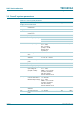
Table 111. Dynamic characteristics of the sound processor
…continued
V
CC
= 8.5 V; T
amb
=25
°
C; see Figure 43; all AC values are given in RMS; treble: 10 kHz filter frequency; treble = 0 dB;
bass: 60 Hz filter frequency; bass = 0 dB; f
audio
= 1 kHz; G
vol
= 0 dB; G
fader
= 0 dB; loudness off; standard output gain
(byte OUTPUT; bit OUTA = 0); R
L
= 10 k
Ω
; C
L
= 1 nF; unless otherwise specified.
Symbol Parameter Conditions Min Typ Max Unit