
Datasheet


TEF6901A_3 © NXP B.V. 2008. All rights reserved.
Product data sheet Rev. 03 — 20 March 2008 92 of 107
NXP Semiconductors
TEF6901A
Integrated car radio
Analog-to-digital converters for I
2
C-bus
Level analog-to-digital converter (8-bit); see
Table 10
V
LEVEL(min)
lower voltage limit of
conversion range
- 0.25 - V
V
LEVEL(max)
upper voltage limit of
conversion range
- 4.25 - V
∆V
LEVEL
bit resolution voltage - 15.7 - mV
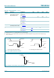
Ultrasonic noise analog-to-digital converter (4-bit); see
Figure 24
∆f
USN(min)
conversion range lower
deviation limit
f
MPXAMOUT
= 150 kHz - 0 - kHz
∆f
USN(max)
conversion range upper
deviation limit
f
MPXAMOUT
= 150 kHz - 100 - kHz
∆f
USN
bit resolution - 6.25 - kHz
Wideband AM analog-to-digital converter (4-bit); see
Figure 24
V
WAM(min)(p-p)
lower voltage limit of
conversion range
(peak-to-peak value)
f
LEVEL
= 21 kHz - 0 - mV
V
WAM(max)(p-p)
upper voltage limit of
conversion range
(peak-to-peak value)
f
LEVEL
= 21 kHz - 800 - mV
∆V
WAM(p-p)
bit resolution voltage
(peak-to-peak value)
- 53.3 - mV
Tone/volume control
Z
i
input impedance measured unbalanced;
pins INAL, INAR, INAC, INBL,
INBR, INC and IND
110 160 - kΩ
Z
o
output impedance pins LFOUT, RFOUT, LROUT
and RROUT
- - 100 Ω
G
s(main)
signal gain from
pins INAL, INAR, INAC,
INBL, INBR, INC and
IND to LFOUT, RFOUT,
LROUT and RROUT
−1 - +1 dB
V
i(max)
maximum input voltage THD = 0.2 %; G
vol
= −6 dB;
pins INAL, INAR, INAC, INBL,
INBR, INC and IND
2- - V
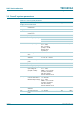
Table 111. Dynamic characteristics of the sound processor
…continued
V
CC
= 8.5 V; T
amb
=25
°
C; see Figure 43; all AC values are given in RMS; treble: 10 kHz filter frequency; treble = 0 dB;
bass: 60 Hz filter frequency; bass = 0 dB; f
audio
= 1 kHz; G
vol
= 0 dB; G
fader
= 0 dB; loudness off; standard output gain
(byte OUTPUT; bit OUTA = 0); R
L
= 10 k
Ω
; C
L
= 1 nF; unless otherwise specified.
Symbol Parameter Conditions Min Typ Max Unit