
Datasheet


TEF6901A_3 © NXP B.V. 2008. All rights reserved.
Product data sheet Rev. 03 — 20 March 2008 82 of 107
NXP Semiconductors
TEF6901A
Integrated car radio
FM channel
FM RF AGC (FM distance mode; LODX = 0)
Inputs: pins FMMIX1IN1 and FMMIX1IN2
[7]
V
i(RF)
RF input voltage for
start of wideband AGC
AGC[1:0] = 11 - 9 - mV
PIN diode drive output: pin IFMAGC
I
source(max)
maximum AGC source
current
AGC[1:0] = 00; KAGC = 0;
V
i(RF)
>V
AGC(start)
;
see
Table 34
−15 −10 −7mA
I
sink(max)
maximum AGC sink
current at AGC recovery
AGC[1:0] = 00; KAGC = 0 7 10 15 mA
I
source
AGC source current AM mode; AGCSW = 1 −6 −4 −2.5 mA
AM mode; AGCSW = 0 - 0 - mA
LODX = 1 (FM local) −0.75 −0.5 −0.35 mA
Voltage for narrow-band AGC: pin LEVEL
V
th
threshold voltage for
narrow-band AGC
KAGC = 1 (keyed AGC) 500 950 1400 mV
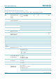
FM mixer 1 (IF1 = 10.7 MHz)
Mixer input: pins FMMIX1IN1 and FMMIX1IN2
[7]
and mixer output: pins MIX1OUT1 and MIX1OUT2
[4]
R
i
input resistance RFGAIN = 0 3 3.8 4.7 kΩ
RFGAIN = 1 1.6 2.0 2.5 kΩ
C
i
input capacitance - 2 4 pF
R
o
output resistance 100 - - kΩ
C
o
output capacitance - 4 6 pF
V
i(RF)(max)
maximum RF input
voltage
1 dB compression point of
FM mixer output voltage
75 100 - mV
V
i(n)(eq)
equivalent input noise
voltage
R
gen
= 200 Ω; noise of R
gen
included; R
L
= 2.6 kΩ
- 2.7 3.2
g
m(conv)
conversion
transconductance I
o
/V
i
RFGAIN = 0 12 18 25
RFGAIN = 1 24 36 50
g
m(conv)(T)
conversion
transconductance
variation with
temperature
- −0.2 × 10
−2
-K
−1
F noise figure R
gen
= 300 Ω
T
amb
= −40 °C - 2.8 - dB
T
amb
=25°C - 3.1 4.6 dB
T
amb
=85°C - 3.5 - dB
R
gen
recommended
generator resistance
- 200 - Ω
IP3 3rd-order intercept point RFGAIN = 0 - 120 - dBµV
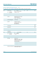
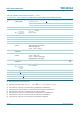
Table 110. Dynamic characteristics of the tuner
…continued
V
CC
= 8.5 V; T
amb
=25
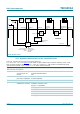
°
C; see Figure 43; all AC values are given in RMS; unless otherwise specified.
Symbol Parameter Conditions Min Typ Max Unit
nV
Hz
----------
mA
V
--------
mA
V
--------