
Datasheet

TEF6901A_3 © NXP B.V. 2008. All rights reserved.
Product data sheet Rev. 03 — 20 March 2008 79 of 107
NXP Semiconductors
TEF6901A
Integrated car radio
C
IAMAGC
source current
generator output
capacitance
-3 - pF
V
VDCPIN
bias voltage for AM PIN
diode
4.5 5 5.5 V
R
VDCPIN
bias source resistance - 150 - Ω
I
bias(max)
maximum bias current source current 20 - - mA
sink current 30 - - µA
AM mixer 1 (IF1 = 10.7 MHz)
Mixer input: pins AMMIX1IN and AMMIX1DEC
R
i
input resistance
[3]
10 13.2 16 kΩ
C
i
input capacitance
[3]
-3 - pF
V
i(max)
maximum input voltage 1 dB compression point of
V
MIX1OUT1-MIX1OUT2
; m=0
500 - - mV
Mixer output: pins MIX1OUT1 and MIX1OUT2
V
o(max)(p-p)
maximum output voltage
(peak-to-peak value)
-12- V
g
m(conv)
conversion
transconductance I
o
/V
i
1.75 2.5 3.25
g
m(conv)(T)
conversion
transconductance
variation with
temperature related to
T
amb
=25°C
T
amb
= −40 °C-1-dB
T
amb
=85°C-−0.2 - dB
R
o
output resistance
[4]
100 - - kΩ
C
o
output capacitance
[4]
-4 7 pF
IP3 3rd-order intercept point R
L
= 2.6 kΩ (AC load between
output pins); ∆f = 300 kHz
135 138 - dBµV
IP2 2nd-order intercept
point
R
L
= 2.6 kΩ (AC load between
output pins)
- 170 - dBµV
V
i(n)(eq)
equivalent input noise
voltage
band limited noise;
R
gen
= 750 Ω; noise of R
gen
included; R
L
= 2.6 kΩ
(AC load between output pins)
- 5.8 8
F noise figure of
AM mixer 1
- 4.5 7.1 dB
AM mixer 2 (IF2 = 450 kHz)
Mixer input: pins IF1IN and IF1DEC
R
i
input resistance
[5]
- 330 - Ω
C
i
input capacitance
[5]
-3 - pF
V
i(max)(p)
maximum input voltage
(peak value)
1 dB compression point of
V
AMMIX2OUT1-AMMIX2OUT2
1.1 1.4 - V
Mixer output: pins AMMIX2OUT1 and AMMIX2OUT2
R
o
output resistance
[6]
50 - - kΩ
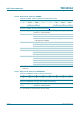
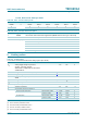
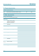
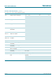
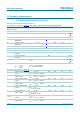
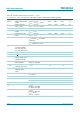
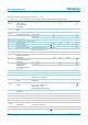
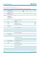
Table 110. Dynamic characteristics of the tuner
…continued
V
CC
= 8.5 V; T
amb
=25
°
C; see Figure 43; all AC values are given in RMS; unless otherwise specified.
Symbol Parameter Conditions Min Typ Max Unit
mA
V
--------
nV
Hz
----------