
Datasheet

TEF6901A_3 © NXP B.V. 2008. All rights reserved.
Product data sheet Rev. 03 — 20 March 2008 42 of 107
NXP Semiconductors
TEF6901A
Integrated car radio
9. Set bits IFCFA and IFNBW to logic 0 to return to normal operation
The bits IFCFA and IFNBW are intended for factory alignment use only. Normal radio
operation requires a setting of bits IFCFA and IFNBW to logic 0.
8.2.11 Write mode: data byte ACD
8.2.12 Write mode: data byte SENSE
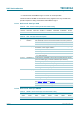
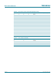
Table 48. ACD - format of data byte 09h with default setting
7 6 5 4 3 2 1 0
ACDLEV ACDLAP1 ACDLAP0 ACDBAL1 ACDBAL0 ACDWAM1 ACDWAM0 HCSFH
01 0 0 1 0 1 0
Table 49. ACD - data byte 09h bit description
Bit Symbol Description
7 ACDLEV level threshold; start level of threshold extension and latch protection
0 = start at LEV = 40 (V
LEVEL
= 0.88 V), normal operation
1 = start at LEV = 48 (V
LEVEL
=1V)
6 and 5 ACDLAP[1:0] latch protection limit; protect against narrow bandwidth locking at high
modulation, low RF signal condition
00 = no protection
01 = low protection
10 = standard protection
11 = high protection
4 and 3 ACDBAL[1:0] control balance; bandwidth control priority towards adjacent channel
(prevent breakthrough) or towards modulation (low distortion)
00 = high adjacent channel priority
01 = medium adjacent channel priority, standard operation
10 = medium modulation priority
11 = high modulation priority
2 and 1 ACDWAM[1:0] WAM threshold; desensitize bandwidth control at detection of WAM
00 = no desensitization on WAM
01 = low sensitivity
10 = medium sensitivity
11 = high sensitivity
0 HCSFH HCC minimum bandwidth; combined control with bit HCSF;
see
Table 57, Table 60 and Figure 26
0 = minimum bandwidth of high cut control is 2.2 kHz or 3.3 kHz
1 = minimum bandwidth of high cut control is 3.9 kHz or 5.6 kHz
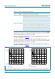
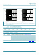
Table 50. SENSE - format of data byte 0Ah with default setting
7 6 5 4 3 2 1 0
CSA3 CSA2 CSA1 CSA0 USS1 USS0 WAS1 WAS0
10000101