
Datasheet


TEF6901A_3 © NXP B.V. 2008. All rights reserved.
Product data sheet Rev. 03 — 20 March 2008 16 of 107
NXP Semiconductors
TEF6901A
Integrated car radio
8.1.2 Read mode: data byte LEVEL
After AF update sampling the level read value is held (indicated by IFCM = 10) for easy
I
2
C-bus read-out. The level detector remains active in the background. The LEV data hold
is released after I
2
C-bus read.
To reduce the influence of modulation in AM mode the LEV information is additionally
filtered by a slow 60 ms detector. Fast level information is made available during
AF update and check tuning.
For standard operation the following level alignment (byte LEVELALGN; see Table 43) is
used:
FM and AM level slope; ∆LEV = 51 (∆V
LEVEL
= 0.80 V) at ∆V
RF
= 20 dB (measured at
V
RF
= 200 µV and V
RF
=20µV)
FM mode level start; LEV = 78 (V
LEVEL
= 1.47 V) at V
RF
=20µV
AM mode level start; LEV = 63 (V
LEVEL
= 1.24 V) at V
RF
=20µV
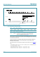
Fig 6. IF counter in FM mode during and after AF update
001aab786
tuning for AF update
2 ms 2 ms 16 mstime
I
2
C-bus
register
2 ms
4 ms
8 ms
16 ms
32 ms
2 ms
2 ms 2 ms 4 ms 8 ms
hold of counter result of f2 until read-out
read-out of counter result f2
2 ms 2 ms 2 ms 2 ms 2 ms 2 ms 2 ms
f1
2 ms
reset
counter time
reset
f1 f2 f2 f1
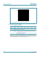
Table 9. LEVEL - format of data byte 1
7 6 5 4 3 2 1 0
LEV7 LEV6 LEV5 LEV4 LEV3 LEV2 LEV1 LEV0
Table 10. LEVEL - data byte 1 bit description
Bit Symbol Description
7 to 0 LEV[7:0] level detector; this byte indicates the LEVEL voltage between
0.25 V (LEV = 0) and 4.25 V (LEV = 255) from the tuner part;
V
LEVEL
=
1
⁄
64
LEV[7:0] + 0.25 V; see Figure 7