
Datasheet


UM11057 All information provided in this document is subject to legal disclaimers. © NXP B.V. 2017. All rights reserved.
User Manual Rev. 1.0 — 9 June 2017 9 of 14
NXP Semiconductors
UM11057
User Manual
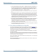
5. Expansion connectors/headers
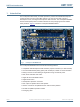
The LPCXpresso845MAX board provides multiple options to add additional circuitry or off
the shelf expansion boards; this section describes these options. For further details
please refer to the board schematics.
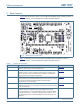
5.1 Arduino UNO Rev 3 expansion connectors
The Arduino UNO Rev 3 compatible connectors provided on the LPCXpresso845MAX
board provide I2C, SPI, UART, PWM and analog function connections to shield boards
that are available from various 3rd part suppliers, or for customer use. The pin mappings
are shown in the tables below. Some connections are shared with the LPCXpresso
connector (P3), as shown.
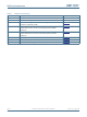
Table 2. Arduino expansion connector pin mappings (Digital connector J1)
J1 Pin Arduino signal LPC845 pin LPCXpresso connector pin
1 I2C SCL PIO0_10 41
2 I2C SDA PIO0_11 40
3 AREF n/a (3.3V) n/a
4 GND n/a (GND) n/a
5 SPI SCK PIO0_6 7
6 SPI MISO PIO0_7 6
7 SPI MOSI PIO1_19 5
8 SPI SSEL PIO1_18 42
9 PWM PIO1_14 n/a
10 PIO0_16 n/a
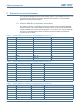
Table 3. Arduino expansion connector pin mappings (Digital connector J2)
J2 pin Arduino signal LPC845 pin LPCXpresso connector pin
1 PIO0_1 43
2 PWM PIO0_28 n/a
3 PWM PIO1_20 n/a
4 PIO1_21 n/a
5 INT/PWM PIO0_20 n/a
6 INT PIO0_21 n/a
7 TX PIO0_25 48
8 RX PIO0_24 49
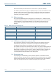
Table 4. Arduino expansion connector pin mappings (Analog connector J6)
J1 Pin Arduino signal LPC845 pin LPCXpresso connector pin
1 A0 PIO0_14 15
2 A1 PIO0_23 16
3 A2 PIO0_19 17
4 A3 PIO0_18 19
5 A4 PIO0_17 20
6 A5 PIO0_29 18