
Datasheet


NXP Semiconductors
UM10973
LPCXpresso54114
UM10973
All information provided in this document is subject to legal disclaimers.
© NXP B.V. 2016. All rights reserved.
User manual
Rev. 1.1 — 25 February 2016
17 of 21
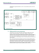
To force entry into one of these boot modes hold down the required button(s), press and
release the Reset button, then release the ISP button(s).
Note that for USB Mass Storage boot to work, a USB host must be connected to J5 and
JP10 must be installed in order to route Vbus to the LPC54114. When the LPC54114 has
been booted in mass storage mode a firmware image (which must be named
firmware.bin) can be virtually “dragged and dropped” onto the board (which appears as a
mass storage device called “CRP DISABLED” on the host computer) using a file
manager utility (such as File Explorer on Windows, or Finder on MacOS). Before
dropping new firmware onto the board the existing firmware.bin needs to be deleted.
This can be useful when the LPC54114 flash has been programmed with code that
disables the SWD debug pins or changes timing settings such that the debug probe has
problems communicating with it. The ISP buttons can be used to force the LPC54114
into a state where the debugger can regain debug control.
The ISP buttons can also be used to trigger an interrupt by configuring the P0_31 / P0_4
pins and associated interrupt controls within your application code.
9.3 WAKE
This button can be used to generate an interrupt by pulling down the P0_24 of the
LPC54114.