
Datasheet


NXP Semiconductors
UM10973
LPCXpresso54114
UM10973
All information provided in this document is subject to legal disclaimers.
© NXP B.V. 2016. All rights reserved.
User manual
Rev. 1.1 — 25 February 2016
15 of 21
7. LED indicators
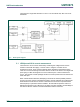
The LPCXpresso54114 board LED locations are shown in Fig 2. A description of each
on-board LED indicator is shown in Table 3.
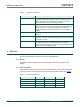
Table 3. LED indicator functions
LED reference
Description
D1
Link2 MCU BOOT0_LED indicator. Reflects the state of Link2 MCU P1_1.
When the boot process fails, D1 will toggle at a 1 Hz rate for 60 seconds.
After 60 seconds, the Link2 MCU is reset. It will be ON when the Link2
MCU is Booting using DFU (See description for JP6).
D2
Tri-color LED – Driven by Target LPC54114 MCU. The red led is driven by
P0_29. The green led is driven by P0_30. The blue led is driven by
P0_31. LEDs are on when the LPC54114 port is output low. To light any
of the tri-color leds, JP6 must have a shunt between pins 1 – 2. By default
the 0Ω resistor at JS17 provides the shunt for JP6. To measure the lowest
possible current from LPC54114 remove the 0Ω resistor at JS17 (remove
+3.3V from led common anode).
D3
Target LPC54114 power LED. This LED is on any time power is applied to
the Target LPC54114 MCU. LED will have a brighter intensity when the
LPC54114 is powered from +3.3V than when powered by +1.8V.
D4
Target Reset LED. This LED is on anytime the Target RESETn is pulled
low.
8. Expansion connectors
The LPCXpresso54114 board includes four expansion connectors plus a PMod™
compatible connector (J3). The expansion connectors (J1, J2, J8 and J9) incorporate an
Arduino Uno revision 3 footprint in their inner rows. Not all connector locations are
populated on the expansion connectors since the LPC54114 does not have enough I/O
to utilize all of the available connections (additional pin locations are provided for
compatibility with future LPCXpresso boards).