
Datasheet


NXP Semiconductors
UM10973
LPCXpresso54114
UM10973
All information provided in this document is subject to legal disclaimers.
© NXP B.V. 2016. All rights reserved.
User manual
Rev. 1.1 — 25 February 2016
12 of 21
5.1.1 LPC54114 Vsense resistor current measurement
The voltage across a series 4.12Ω resistor with the target LPC54114 VDD can be
manually measured at P2 on the PCB. The voltmeter positive probe is applied to P2 pin
1 (square pad) and negative probe to P2 pin 2. Use Ohm’s law to calculate the current
(LPC54114 current = measured voltage / 4.12Ω). As an example if the measured
voltage is 10mV, then 10e-3 / 4.12Ω = 2.44mA. Note that the input current to the
MAX9634 used in the on-board current measurement will be included in the voltage
measured across this resistor.
5.1.2 LPC54114 VDD current measurement using a current meter
A current meter may be inserted at JP4 to measure the LPC54114 VDD input current.
The 0Ω resistor at JS11 must be removed and the current meter connected at the
positive input at JP4 pin 1 (square pad) and negative input at pin 2.
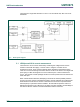
5.1.3 LPC54114 VDD current measurement
The LPCXpresso54114 board has an on-board current measurement circuit consisting of
a MAX9634T (U5) current monitor chip and a 12-bit ADC (ADC122S021, U11) with a 12-
bit sample at 50k to 200ksps. The on-board MAX9634T current monitor measures the
voltage across the LPC54114 VDD vsense resistors; either 8.24Ω or 4.12 Ω if JP3 is
installed. The MAX9634 multiplies the sense voltage by 25 to provide a voltage range
suitable for the ADC to measure. A 2-input analog mux selects between the LPC54114
current monitor and the output on a MAX9634T current monitor chip on an expansion
board (with compatible current measurement circuit on-board). The current measurement
circuit is controlled by the Link2 processor and is not user programmable. Power
measurement utilities to use this feature are available in the LPCXpresso IDE installation.
Due to input offset voltage variations in the MAX9634, the current measurement circuit is
not recommended for measuring current below 150uA. See Fig 5 as a guideline for
measurement error versus measured current.