
Datasheet


NXP Semiconductors
UM10973
LPCXpresso54114
UM10973
All information provided in this document is subject to legal disclaimers.
© NXP B.V. 2016. All rights reserved.
User manual
Rev. 1.1 — 25 February 2016
11 of 21
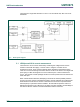
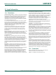
The LPC54114 Target VDD selection of 1.8V or 3.3V is made at JP9, with 3.3V set as
the default.
Fig 4. Board power diagram
5.1 LPCXpresso54114 current measurement
The LPC54114 current can be measured by measuring the voltage across a sense
resistor in series with the supply, a current meter or using the on board current
measurement circuit. Each of these methods will be described in subsections below.
There is no current monitoring of the Link2 section circuits on the board. The Target side
power going to LEDs and support ICs is not monitored by the current measurement
circuit. The LPC54114 LQFP package has the core and IO power both sourced from the
same VDD pins.
When a shield board is attached, attempting to measure the lowest possible power the
LPC54114 IO pins must be configured according to how the software has configured the
shield board to ensure there is no extra current from the LPC54114 IO ports that have
external pull-up or pull-down resistors enabled. JS19 should be opened to ensure no
leakage through the tri-color LED and +3.3V supply, and JP6 opened to avoid leakage to
the Link2 via the I2C and SPI connections between it and the LPC54114.