
User guide

6.3.2 Signals on the board
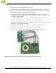
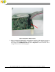
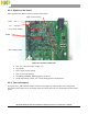
Main signals on the MP TX board are shown in this figure.
Figure 43 Test Points on WCT_MP
• TP1: Vcc, controller input voltage 3.3V
• TP3: GND
• TP13: Input current sensing
• TP6: Coil current sensing
• TP47&48: PWM1&2, PWM signals to pre-driver
• TP49: Rail voltage, VINA, 12V except during Q factor measurement
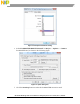
6.3.3 Test environment
Set up the WCT_MP test environment as shown in this figure by using the DC power supply and
electronic load for input source and output load. Get system efficiency by measuring input and output
power.
Input current sensing
PWM
Vcc
GND
Coil current sensing
Rail Voltage,VINA
WCT1012 15W Single Coil TX V3.0 Reference Design System User’s Guide, Rev. 0, 09/2015
30 Freescale Semiconductor