
User guide
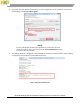
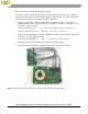
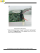
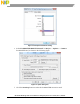
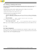
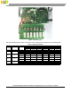
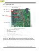

Figure 42 Working syste
The defined LED display modes for defferent TX working states are shown in the following table:
Table 1 LED display modes
Standby
Charging
Charge
Complete
FOD Fault
TX Fault RX Fault
LED1 Off Blink slow Off On On On
LED2 Blink slow On On Off Off Off
LED1 Off Blink slow On Off Off Off
LED2 Off Off Off Blink fast Blink fast Blink fast
LED1 Off On Off Off Off Off
LED2 Off Off Off On Blink slow Blink slow
LED1 Off Blink slow On Blink fast Blink fast Blink fast
LED2 - - - - - -
LED
Configure
Option
Description
LED #
LED Operational States
Default
Default Choice
Option-1
Choice-1
Option-2
Choice-2
Option-3
Choice-3
WCT1012 15W Single Coil TX V3.0 Reference Design System User’s Guide, Rev. 0, 09/2015
Freescale Semiconductor 29