
User guide


Preparing the MPC8568E-MDS-PB Board
Preparing for Bare Board Development or for Linux® OS Customization
16
MPC8568E Kit Configuration Guide
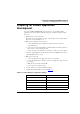
2. Make power connections.
a. Connect the supplied 5 Volt power supply to board power connector P8.
b. Connect the supplied power cable between the power supply and a surge-protected
power strip.
c. Make sure the power strip is turned OFF.
d. Connect the power strip to line power.
e. Turn on the power supply.
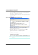
3. Perform initial board power up.
a. Press the board power switch (SW5).
The processor board powers up. LD2 and LD7 display a constant green light. LD1
flashes orange once at the end of the reset sequence.
b. Press the board power switch again to turn off power.
The board powers down.
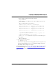
4. Connect the USB TAP debug probe.
a. Connect the USB TAP debug probe’s JTAG/COP connector to header P5 of the
processor board.
NOTE The red wire of the USB TAP probe’s JTAG/COP connector goes to pin 1 of
board header P5.
b. Connect the supplied USB cable to the USB TAP probe.
c. Connect the USB cable to a USB 2.0 port of your computer.
NOTE Do not install the driver for the USB TAP now. If the Found New Hardware
Wizard appears, click Cancel.
5. Make board-to-computer serial connection.
a. Connect the RJ45 plug of the supplied joined adapter cable to board serial
connector RS232-1,2.
b. Connect one end of the supplied RS-232 straight-through serial cable to the Port 1
DB9 connector of the joined adapter cable.
c. Connect the other end of the RS-232 serial cable to a serial port of your computer.
The MPC8568E-MDS-PB processor board is now ready to execute binaries under control
of the CodeWarrior debugger. See “Creating and Debugging a Bare Board Project” on
page 43 for instructions.
The processor board is also ready to be flashed with a custom Linux image. See “Using
the MPC8568E-MDS-PB BSP” on page 55 for instructions.