
Datasheet
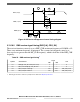

6. Thermal characterization parameter indicating the temperature difference between package top and the junction
temperature per JEDEC JESD51-2.
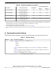
Table 55. Thermal characteristics, 516-ball MAPBGA package
Characteristic Symbol Value Unit
Junction to Ambient
1, 2
Natural Convection (Single layer board) R
ΘJA
28.5 °C/W
Junction to Ambient
1, 3
Natural Convection (Four layer board 2s2p) R
ΘJA
20.0 °C/W
Junction to Ambient (@200 ft./min., Single layer board) R
ΘJMA
21.3 °C/W
Junction to Ambient (@200 ft./min., Four layer board 2s2p) R
ΘJMA
15.5 °C/W
Junction to Board
4
R
ΘJB
8.8 °C/W
Junction to Case
5
R
ΘJC
4.8 °C/W
Junction to Package Top
6
Natural Convection Ψ
JT
0.2 °C/W
1. Junction temperature is a function of on-chip power dissipation, package thermal resistance, mounting site (board)
temperature, ambient temperature, air flow, power dissipation of other components on the board, and board thermal
resistance.
2. Per JEDEC JESD51-2 with the single layer board horizontal. Board meets JESD51-9 specification.
3. Per JEDEC JESD51-6 with the board horizontal.
4. Thermal resistance between the die and the printed circuit board per JEDEC JESD51-8. Board temperature is measured
on the top surface of the board near the package.
5. Indicates the average thermal resistance between the die and the case top surface as measured by the cold plate method
(MIL SPEC-883 Method 1012.1) with the cold plate temperature used for the case temperature.
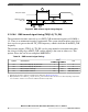
6. Thermal characterization parameter indicating the temperature difference between package top and the junction
temperature per JEDEC JESD51-2.
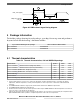
4.1.1 General notes for thermal characteristics
An estimation of the chip junction temperature, T
J
, can be obtained from the equation:
where:
T
A
= ambient temperature for the package (°C)
R
ΘJA
= junction-to-ambient thermal resistance (°C/W)
P
D
= power dissipation in the package (W)
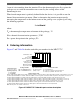
The thermal resistance values used are based on the JEDEC JESD51 series of standards
to provide consistent values for estimations and comparisons. The difference between the
values determined for the single-layer (1s) board compared to a four-layer board that has
two signal layers, a power and a ground plane (2s2p), demonstrate that the effective
thermal resistance is not a constant. The thermal resistance depends on the:
• Construction of the application board (number of planes)
• Effective size of the board which cools the component
Package information
MPC5777C Microcontroller Data Sheet Data Sheet, Rev. 13, 08/2018.
84 NXP Semiconductors