
Datasheet
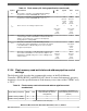
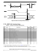
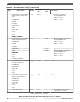

Table 33. Flash memory AC timing specifications (continued)
Symbol Characteristic Min Typical Max Units
t
done
Time from 0 to 1 transition on the MCR-EHV bit initiating a
program/erase until the MCR-DONE bit is cleared.
— — 5 ns
t
dones
Time from 1 to 0 transition on the MCR-EHV bit aborting a
program/erase until the MCR-DONE bit is set to a 1.
— 16
plus four
system
clock
periods
20.8
plus four
system
clock
periods
μs
t
drcv
Time to recover once exiting low power mode. 16
plus seven
system
clock
periods.
— 45
plus seven
system
clock
periods
μs
t
aistart
Time from 0 to 1 transition of UT0-AIE initiating a Margin Read
or Array Integrity until the UT0-AID bit is cleared. This time also
applies to the resuming from a suspend or breakpoint by
clearing AISUS or clearing NAIBP
— — 5 ns
t
aistop
Time from 1 to 0 transition of UT0-AIE initiating an Array
Integrity abort until the UT0-AID bit is set. This time also applies
to the UT0-AISUS to UT0-AID setting in the event of a Array
Integrity suspend request.
— — 80
plus fifteen
system
clock
periods
ns
t
mrstop
Time from 1 to 0 transition of UT0-AIE initiating a Margin Read
abort until the UT0-AID bit is set. This time also applies to the
UT0-AISUS to UT0-AID setting in the event of a Margin Read
suspend request.
10.36
plus four
system
clock
periods
— 20.42
plus four
system
clock
periods
μs
3.12.6 Flash memory read wait-state and address-pipeline control
settings
The following table describes the recommended settings of the Flash Memory
Controller's PFCR1[RWSC] and PFCR1[APC] fields at various flash memory operating
frequencies, based on specified intrinsic flash memory access times of the C55FMC array
at 150°C.
Table 34. Flash memory read wait-state and address-pipeline control
combinations
Flash memory frequency RWSC APC
Flash memory read latency on
mini-cache miss (# of f
PLATF
clock periods)
Flash memory read latency on
mini-cache hit (# of f
PLATF
clock
periods)
0 MHz < f
PLATF
≤ 33 MHz 0 0 3 1
33 MHz < f
PLATF
≤ 100 MHz 2 1 5 1
Table continues on the next page...
Electrical characteristics
MPC5777C Microcontroller Data Sheet Data Sheet, Rev. 13, 08/2018.
NXP Semiconductors 51