
Datasheet
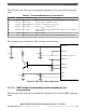

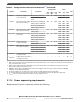

The following table describes the supply stability capacitances required on the device for
proper operation.
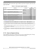
Table 28. Device power supply integration
Symbol Parameter Conditions
Value
1
Unit
Min Typ Max
C
LV
Minimum V
DD
external bulk capacitance
2, 3
LDO mode 4.7 — — μF
SMPS mode 22 — — μF
C
SMPSPWR
Minimum SMPS driver supply capacitance — 22 — — μF
C
HV_PMC
Minimum V
DDPMC
external bulk capacitance
4, 5
LDO mode 22 — — μF
SMPS mode 22 — — μF
C
HV_IO
Minimum V
DDEx
/V
DDEHx
external capacitance
2
— — 4.7
6
— μF
C
HV_FLA
Minimum V
DD_FLA
external capacitance
7
— 1.0 2.0 — μF
C
HV_ADC_EQA/B
Minimum V
DDA_EQA/B
external capacitance
8
— 0.01 — — μF
C
REFEQ
Minimum REF
BYPCA/B
external capacitance
9
— 0.01 — — μF
C
HV_ADC_SD
Minimum V
DDA_SD
external capacitance
10
— 1.0 2.2 — μF
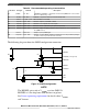
1. See Figure 14 for capacitor integration.
2. Recommended X7R or X5R ceramic low ESR capacitors, ±15% variation over process, voltage, temperature, and aging.
3. Each V
DD
pin requires both a 47 nF and a 0.01 μF capacitor for high-frequency bypass and EMC requirements.
4. Recommended X7R or X5R ceramic low ESR capacitors, ±15% variation over process, voltage, temperature, and aging.
5. Each V
DDPMC
pin requires both a 47 nF and a 0.01 μF capacitor for high-frequency bypass and EMC requirements.
6. The actual capacitance should be selected based on the I/O usage in order to keep the supply voltage within its operating
range.
7. The recommended flash regulator composition capacitor is 2.0 μF typical X7R or X5R, with -50% and +35% as min and
max. This puts the min cap at 0.75 μF.
8. For noise filtering it is recommended to add a high frequency bypass capacitance of 0.1 μF between V
DDA_EQA/B
and
V
SSA_EQ
.
9. For noise filtering it is recommended to add a high frequency bypass capacitance of 0.1 μF between REF
BYPCA/B
and V
SS
.
10. For noise filtering it is recommended to add a high frequency bypass capacitance of 0.1 μF between V
DDA_SD
and
V
SSA_SD
.
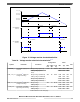
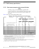
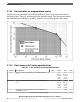
3.11.3 Device voltage monitoring
The LVD/HVDs for the device and their levels are given in the following table. Voltage
monitoring threshold definition is provided in the following figure.
Electrical characteristics
MPC5777C Microcontroller Data Sheet Data Sheet, Rev. 13, 08/2018.
44 NXP Semiconductors