
Datasheet
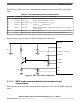

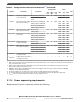
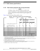
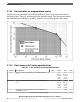

Table 26. Recommended operating characteristics
Part name Part type Nominal Description
Q1 p-MOS 3 A - 20 V SQ2301ES / FDC642P or equivalent: low threshold p-MOS, Vth < 2.0 V, Rdson
@ 4.5 V < 100 mΩ, Cg < 5 nF
D1 Schottky 2 A - 20 V SS8P3L or equivalent: Vishay™ low Vf Schottky diode
L Inductor 3-4 μH - 1.5 A Buck shielded coil low ESR
CI Capacitor 22 μF - 20 V Ceramic capacitor, total ESR < 70 mΩ
CE Capacitor 0.1 μF - 7 V Ceramic—one capacitor for each V
DD
pin
CV Capacitor 22 μF - 20 V Ceramic V
DDPMC
(optional 0.1 μF capacitor in parallel)
CD Capacitor 22 μF - 20 V Ceramic supply decoupling capacitor, ESR < 50 mΩ (as close as possible to
the p-MOS source)
R Resistor 2.0-4.7 kΩ Pullup for power p-MOS gate
CB Capacitor 22 μF - 20 V Ceramic, connect 100 nF capacitor in parallel (as close as possible to package
to reduce current loop from V
DDPWR
to V
SSPWR
)
The following diagram shows the SMPS configuration connection.
CD
CV
CI CE
CB
VDDPMC
REGSEL
VSSPMC (clean ground)
VDDPWR
REGCTL
VSSPWR
VDD
VSS
L
R
D1
Q1
Figure 13. SMPS configuration
NOTE
The REGSEL pin is tied to V
DDPMC
to select SMPS. If
REGSEL is 0, the chip boots with the linear regulator.
See Power sequencing requirements for details about V
DDPMC
and V
DDPWR
.
Electrical characteristics
MPC5777C Microcontroller Data Sheet Data Sheet, Rev. 13, 08/2018.
42 NXP Semiconductors