
Datasheet
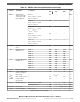
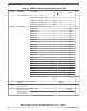
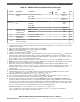
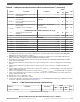

Table 18. SDADC electrical specifications (continued)
Symbol Parameter Conditions
Value
Unit
Min Typ Max
F
rolloff
Stop band attenuation [0.5 * f
ADCD_S
, 1.0 * f
ADCD_S
] 40 — — dB
[1.0 * f
ADCD_S
, 1.5 * f
ADCD_S
] 45 — —
[1.5 * f
ADCD_S
, 2.0 * f
ADCD_S
] 50 — —
[2.0 * f
ADCD_S
, 2.5 * f
ADCD_S
] 55 — —
[2.5 * f
ADCD_S
, f
ADCD_M
/2] 60 — —
δ
GROUP
Group delay Within pass band: Tclk is f
ADCD_M
/ 2 — — — —
OSR = 24 — — 235.5 Tclk
OSR = 28 — — 275
OSR = 32 — — 314.5
OSR = 36 — — 354
OSR = 40 — — 393.5
OSR = 44 — — 433
OSR = 48 — — 472.5
OSR = 56 — — 551.5
OSR = 64 — — 630.5
OSR = 72 — — 709.5
OSR = 75 — — 696
OSR = 80 — — 788.5
OSR = 88 — — 867.5
OSR = 96 — — 946.5
OSR = 112 — — 1104.5
OSR = 128 — — 1262.5
OSR = 144 — — 1420.5
OSR = 160 — — 1578.5
OSR = 176 — — 1736.5
OSR = 192 — — 1894.5
OSR = 224 — — 2210.5
OSR = 256 — — 2526.5
Distortion within pass band –0.5/
f
ADCD_S
— +0.5/ f
ADCD_S
—
f
HIGH
High pass filter 3 dB
frequency
Enabled — 10e–5*
fADCD_S
— —
t
STARTUP
Startup time from
power down state
— — — 100 μs
t
LATENCY
Latency between input
data and converted
data when input mux
does not change
15
HPF = ON — — δ
GROUP
+
f
ADCD_S
—
HPF = OFF — — δ
GROUP
Table continues on the next page...
Electrical characteristics
MPC5777C Microcontroller Data Sheet Data Sheet, Rev. 13, 08/2018.
32 NXP Semiconductors