
Datasheet
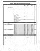
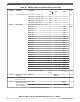
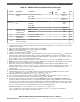
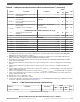
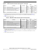
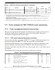

Table 18. SDADC electrical specifications (continued)
Symbol Parameter Conditions
Value
Unit
Min Typ Max
THD
SE150
Total harmonic
distortion in single-
ended mode, 150
Ksps output rate
Gain = 1
4.5 V < V
DDA_SD
< 5.5 V
V
RH_SD
= V
DDA_SD
68 — — dBFS
Gain = 2
4.5 V < V
DDA_SD
< 5.5 V
V
RH_SD
= V
DDA_SD
68 — —
Gain = 4
4.5 V < V
DDA_SD
< 5.5 V
V
RH_SD
= V
DDA_SD
66 — —
Gain = 8
4.5 V < V
DDA_SD
< 5.5 V
V
RH_SD
= V
DDA_SD
68 — —
Gain = 16
4.5 V < V
DDA_SD
< 5.5 V
V
RH_SD
= V
DDA_SD
68 — —
SFDR Spurious free dynamic
range
Any GAIN 60 — — dB
Z
DIFF
Differential input
impedance
10, 11
GAIN = 1 1000 1250 1500 kΩ
GAIN = 2 600 800 1000
GAIN = 4 300 400 500
GAIN = 8 200 250 300
GAIN = 16 200 250 300
Z
CM
Common Mode input
impedance
11, 12
GAIN = 1 1400 1800 2200 kΩ
GAIN = 2 1000 1300 1600
GAIN = 4 700 950 1150
GAIN = 8 500 650 800
GAIN = 16 500 650 800
R
BIAS
Bare bias resistance — 110 144 180 kΩ
ΔV
INTCM
Common Mode input
reference voltage
13
— –12 — +12 %
V
BIAS
Bias voltage — — V
RH_SD
/2 — V
δV
BIAS
Bias voltage accuracy — –2.5 — +2.5 %
CMRR Common mode
rejection ratio
— 20 — — dB
R
Caaf
Anti-aliasing filter External series resistance — — 20 kΩ
Filter capacitances 220 — — pF
f
PASSBAND
Pass band
9
— 0.01 — 0.333 * f
ADCD_S
kHz
δ
RIPPLE
Pass band ripple
14
0.333 * f
ADCD_S
–1 — 1 %
Table continues on the next page...
Electrical characteristics
MPC5777C Microcontroller Data Sheet Data Sheet, Rev. 13, 08/2018.
NXP Semiconductors 31