
Datasheet
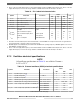
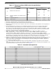
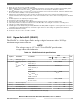
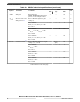
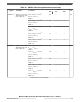
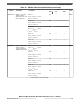
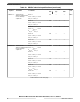

Table 14. External oscillator (XOSC) electrical specifications
(continued)
Symbol Parameter Conditions
Value
Unit
Min Max
g
m
Oscillator transconductance
5
Low 3 10 mA/V
Medium 10 27
High 12 35
V
EXTAL
Oscillation amplitude on the EXTAL pin after
startup
6
— 0.5 1.6 V
V
HYS
Comparator hysteresis — 0.1 1.0 V
I
XTAL
XTAL current
6, 7
— — 14 mA
1. This value is determined by the crystal manufacturer and board design.
2. Proper PC board layout procedures must be followed to achieve specifications.
3. Crystal recovery time is the time for the oscillator to settle to the correct frequency after adjustment of the integrated load
capacitor value.
4. See crystal manufacturer's specification for recommended load capacitor (C
L
) values.The external oscillator requires
external load capacitors when operating in a "low" transconductance range. Account for on-chip stray capacitance
(C
S_EXTAL
/C
S_XTAL
) and PCB capacitance when selecting a load capacitor value. When operating in a "medium" or "high"
transconductance range, the integrated load capacitor value is selected via software to match the crystal manufacturer's
specification, while accounting for on-chip and PCB capacitance.
5. Select a "low," "medium," or "high" setting using the UTEST Miscellaneous DCF client's XOSC_LF_EN and
XOSC_EN_HIGH fields. "Low" is the setting commonly used for crystals at 8 MHz, "medium" is commonly used for
crystals greater than 8 MHz to 20 MHz, and "high" is commonly used for crystals greater than 20 MHz to 40 MHz.
However, the user must characterize carefully to determine the best g
m
setting for the intended application because crystal
load capacitance, board layout, and other factors affect the g
m
value that is needed. The user may need an additional
Rshunt to optimize g
m
depending on the system environment. Use of overtone crystals is not recommended.
6. Amplitude on the EXTAL pin after startup is determined by the ALC block (that is, the Automatic Level Control Circuit). The
function of the ALC is to provide high drive current during oscillator startup, while reducing current after oscillation to
reduce power, distortion, and RFI, and to avoid over-driving the crystal. The operating point of the ALC is dependent on
the crystal value and loading conditions.
7. I
XTAL
is the oscillator bias current out of the XTAL pin with both EXTAL and XTAL pins grounded. This is the maximum
current during startup of the oscillator. The current after oscillation is typically in the 2–3 mA range and is dependent on the
load and series resistance of the crystal. Test circuit is shown in Figure 7.
Table 15. Selectable load capacitance
load_cap_sel[4:0] from DCF record Load capacitance
1, 2
(pF)
00000 1.8
00001 2.8
00010 3.7
00011 4.6
00100 5.6
00101 6.5
00110 7.4
00111 8.4
01000 9.3
01001 10.2
01010 11.2
Table continues on the next page...
Electrical characteristics
MPC5777C Microcontroller Data Sheet Data Sheet, Rev. 13, 08/2018.
22 NXP Semiconductors