
Datasheet
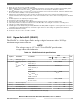

4. Noise on the V
DD
supply with frequency content below 40 kHz and above 50 MHz is filtered by the PLL. Noise on the V
DD
supply with frequency content in the range of 40 kHz – 50 MHz must be filtered externally to the device.
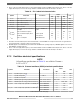
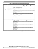
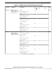
Table 13. PLL1 electrical characteristics
Symbol Parameter Conditions
Value
Unit
Min Typ Max
f
PLL1IN
PLL1 input clock
1
— 38 — 78 MHz
Δ
PLL1IN
PLL1 input clock duty cycle
1
— 35 — 65 %
f
PLL1VCO
PLL1 VCO frequency — 600 — 1250 MHz
f
PLL1PHI
PLL1 output clock PHI — 4.762 — 264/300
2
MHz
t
PLL1LOCK
PLL1 lock time — — — 100 μs
|Δ
PLL1PHISPJ
| PLL1_PHI single period peak-to-
peak jitter
f
PLL1PHI
= 200 MHz, 6-
sigma
— — 500
3
ps
f
PLL1MOD
PLL1 modulation frequency — — — 250 kHz
|δ
PLL1MOD
| PLL1 modulation depth (when
enabled)
Center spread 0.25 — 2 %
Down spread 0.5 — 4 %
I
PLL1
PLL1 consumption FINE LOCK state — — 6 mA
1. PLL1IN clock retrieved directly from either internal PLL0 or external XOSC clock. Input characteristics are granted when
using internal PLL0 or external oscillator in functional mode.
2. 264 MHz applies to the MPC5777C part number with 264 MHz max operating frequency. 300 MHz applies to the version
with 300 MHz operating frequency
3. Noise on the V
DD
supply with frequency content below 40 kHz and above 50 MHz is filtered by the PLL. Noise on the V
DD
supply with frequency content in the range of 40 kHz – 50 MHz must be filtered externally to the device.
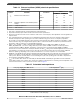
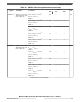
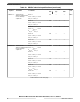
3.7.2 Oscillator electrical specifications
NOTE
All oscillator specifications in Table 14 are valid for V
DDEH6
=
3.0 V to 5.5 V.
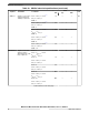
Table 14. External oscillator (XOSC) electrical specifications
Symbol Parameter Conditions
Value
Unit
Min Max
f
XTAL
Crystal frequency range — 8 40 MHz
t
cst
Crystal start-up time
1, 2
T
J
= 150 °C — 5 ms
t
rec
Crystal recovery time
3
— — 0.5 ms
V
IHEXT
EXTAL input high voltage (external reference) V
REF
= 0.28 * V
DDEH6
V
REF
+ 0.6 — V
V
ILEXT
EXTAL input low voltage (external reference) V
REF
= 0.28 * V
DDEH6
— V
REF
– 0.6 V
C
S_EXTAL
Total on-chip stray capacitance on EXTAL pin
4
416-ball MAPBGA 2.3 3.0 pF
516-ball MAPBGA 2.1 2.8
C
S_XTAL
Total on-chip stray capacitance on XTAL pin
4
416-ball MAPBGA 2.3 3.0 pF
516-ball MAPBGA 2.2 2.9
Table continues on the next page...
Electrical characteristics
MPC5777C Microcontroller Data Sheet Data Sheet, Rev. 13, 08/2018.
NXP Semiconductors 21