
User guide

MPC5668EVB Users Manual Rev 0.1 May 2009
MPC5668EVBUM/D Page 14 of 29
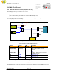
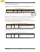
3.4.1 Debug Connector Pinouts
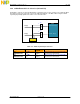
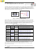
The EVB is fitted with 14-pin JTAG / ONCE and 38-pin Nexus debug connectors. The following diagram
shows the 14-pin JTAG / ONCE connector pinout (0.1” keyed header).
Figure 3-8. MPC5668 JTAG / ONCE Connector
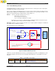
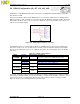
The Nexus module used on the MPC5668 family uses the JTAG pins (for control of the Nexus block) along
with additional Nexus pins for trace messages. Nexus mode is entered by a JTAG sequence whereby the
Nexus EVTI pin is sampled on the rising edge of the JTAG TRST pin. If the EVTI is asserted on TRST, Nexus
is enabled.
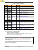
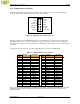
The table below shows the pinout of the 38-pin MICTOR Nexus connector for the MPC5668
Table 3-13. NEXUS Debug Connector Pinout
Pin
No
Function
Connection
Pin
No
Function
Connection
1 Reserved --- 2 Reserved ---
3 Reserved --- 4 Reserved ---
5 MDO[9] MCU M5 6 CLKOUT MCU PK9
7 Vendor I/O-2 TP25 8 MDO[8] MCU L5
9 Reset-In Reset CCT 10 EVTI MCU M11
11 TDO MCU M3 12 VREF 3.3V Reg
13 MDO[10] MCU M6 14 RDY TP29
15 TCLK MCU P3 16 MDO[7] MCU K5
17 TMS MCU L3 18 MDO[6] MCU J5
19 TDI MCU J3 20 MDO[5] MCU J6
21 TRST JCOMP 22 MDO[4] MCU H6
23 MDO[11] MCU M7 24 MDO[3] MCU H5
25 Tool I/O-3 TP26 26 MDO[2] MCU G5
27 Tool I/O-2 TP27 28 MDO[1] MCU F5
29 Tool I/O-1 TP28 30 MDO[0] MCU E5
31 UBATT 12V Vin 32 EVTO MCU M12
33 UBATT
12V Vin 34 MCK0 MCU M10
35 Tool I/O-0 TP30 36 MSE1 MCU M9
37 VALTREF
3.3V Reg 38 MSEO MCU M8
Note - In order to preserve the ability to accurately measure power consumption on the MCU pins, the JTAG
and Nexus connector reference voltages will be sourced directly from the 5V regulator or from the 12V
unregulated input.
2 VSS
4 VSS
6 VSS
8 N/C
10 TMS
12 VSS
14 JCOMP
TDI 1
TDO3
TCLK 5
5v EVTI 7
RESET 9
VDDE2 11
RDY 13