
User guide

MPC5668EVB Users Manual Rev 0.1 May 2009
MPC5668EVBUM/D Page 7 of 29
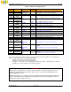
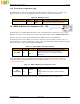
Table 3-2 MCU Power Supply Jumpers
Power
Domain
Jumper Position PCB
Legend
Description
5.0V J49 (VDDA)
FITTED
(D)
MCU VDDA is powered from 5V linear regulator
REMOVED MCU VDDA User powered from J49 Pin 2
5.0V /
3.3V
J
4
6
(VRC)
1-2
(D)
5V VRC is supplied from the 5V switching regulator
2-3 3.3v VRC is supplied from the 3.3V switching regulator
J
47
(VRCSEL)
1-2
(D)
INT 3.3 V internal voltage regulator enabled (5 V mode)
2-3 EXT 3.3 V supplied external (3.3 V mode)
J
43
(VDDE1)
1-2
(D)
5.0v MCU VDDE1 is powered from 5v
2-3 3.3V MCU VDDE1 is powered from 3.3V
J
42
(VDDE2)
1-2
(D)
5.0v MCU VDDE2 is powered from 5v
2-3 3.3V MCU VDDE2 is powered from 3.3V
J
44
(VDDE3)
1-2
(D)
5.0v MCU VDDE3 is powered from 5v
2-3
3.3V
MCU VDDE3 is powered from 3.3V
J
4
1
(VDDE4)
1-2
(D)
5.0v MCU VDDE4 is powered from 5v
2-3
3.3V
MCU VDDE4 is powered from 3.3V
3.3V
J
48
(VDD33)
FITTED MCU VDD33 pin is powered from switching regulator
REMOVED
(D)
MCU VDD33 pin is not powered externally
J
50
(VDDSYN)
FITTED MCU VDDSYN pin is powered from switching
regulator
REMOVED
(D)
MCU VDDSYN pin is not powered externally
3.3v/
2.5V
J
45
(VDDEMLB)
1-2
(D)
2.5V MCU VDD pin is powered from 1.5v switching
regulator
2-3 3.3V MCU VDD pin is not powered externally
The jumper configuration shown in Table 3-2, details the default state of the EVB. In this configuration all
power is supplied from the Linear and Switching regulators.
- VDDA is connected to the 5.0V Linear regulator
- VRC is connected to the 5.0V switching regulator
- VRCSEL is connected to logic 1 enabling the internal 3.3V regulator – J48 and J50 are removed.
- VDDE[1..4] are connected to the 5.0V switching regulator
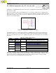
CAUTION
When jumper J47 (VRCSEL) is in position 1-2 (INT), the MCU’s 3.3V internal voltage regulators are
enabled and supply power to the 3.3V power domains. In this case, jumpers J48 (VDD33) and J50
(VDDSYN) must be removed.
Similarly, when jumper J47 is removed, no power is supplied to the MCU internal voltage regulators and
jumpers J48 (VDD33) and J50 (VDDSYN) must be fitted to power the respective MCU pins. The 3.3V
regulator must also be enabled in this case.