
User guide

MPC5668EVB Users Manual Rev 0.1 May 2009
MPC5668EVBUM/D Page 6 of 29
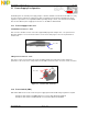
The MCU power supply
jumpers are located in the
centre of the EVB in a box
titled “MCU Supply”
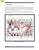
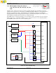
3.1.5 MCU Supply Routing and Jumpers
(J41, J42, J43, J44, J45, J46, J47, J48, J49,
J50)
The MCU can be operated in 5v and 3.3v modes by changing J46. When in 5v mode MCU has internal
regulators that can generate the 3.3V supplies for VDDSYN and VDD33. Whilst this is the intended mode of
operation for the MCU when VRC = 5v the EVB allows the internal MCU regulators to be disabled by
changing VRCSEL to EXT and applying external voltages to the VDDSYN and VDD33 inputs. When in 3.3v
mode VDDSYN and VDD33 inputs must always be supplied externally.
The VDDE[1..4] pins control the pad voltages over 4 groupings of pads (see the MCU reference manual for
details). Jumpers J41 - J34 allow the VDDEx pins to be connected to the 5.0v or 3.3V switching regulators.
The VDDEMLB domain can be 3.3v or 2.5v selectable by J45.
Figure 3-4. Power Supply Routing
MCU Powe
r
5V Switcher
3.3V
Switcher
2.5V
Switcher
5V Linear
12V
VDD33
VDDSYN
VDDE1
VRC
VDDA
VDDE2
VDDE3
J46
J50
J48
1
1
1
J49
VDDE4
VDDEMLB
J43
J45
1
1
1
J41
1
J44
1
J42
1
VRCSEL
1
0
J47
VRCSEL
1
INTernal
EXTernal