
Datasheet


Electrical characteristics
i.MX 8QuadXPlus and 8DualXPlus Automotive and Infotainment Applications Processors, Rev. 0, 11/2018
PRELIMINARYNXP Semiconductors 97
4.10.16 USB 2.0 PHY Parameters
4.10.16.1 USB 2.0 PHY Transmitter specifications
This section describes the transmitter specifications for USB2.0 PHY.
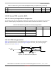
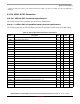
4.10.16.1.1 USB 2.0 PHY full-speed/low-speed transmitter specifications
The following table lists the full-speed/low-speed (FS/LS) transmitter specifications for USB2.0 PHY.
2
Fbaud_rate: Baud rate frequency. The maximum baud rate the UART can support is (LPUART_clk frequency)/(SBR[12:0] ×
(OSR+1)).
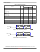
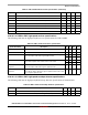
Table 95. USB 2.0 PHY FS/LS transmitter specifications
Symbol Description Min Typ Max Units
VOL Output Voltage Low 0 — 0.3 V
VOH Output Voltage High (Driven) 2.8 — 3.6 V
VOSE1 Single Ended One (SE1) 0.8 — — V
VCRS Output Signal Cross Over Voltage 1.3 — 2.0 V
TFR Driver Rise Time - FS 4 — 20 ns
TLR Driver Rise Time - LS 75 — 300 ns
TFF Driver Fall Time - FS 4 — 20 ns
TLF Driver Fall Time - LS 75 — 300 ns
TFRFM Differential Rise and Fall Time Matching - FS 90 — 111.11 %
TLRFM Differential Rise and Fall Time Matching - LS 80 — 125 %
ZHSDRV Driver Output Resistance (Also serves as HS Termination) 40.5 — 49.5 Ω
TDJ1 Source Jitter (Next Transition) - FS -3.5 — 3.5 ns
TDJ2 Source Jitter (Paired Transition) - FS -4 — 4 ns
TFDEOP Source Jitter (Differential to SE0 transition) - FS -2 — 5 ns
TFEOPT Source SE0 interval of EOP - FS 160 — 175 ns
TDDJ1 Source Jitter in downstream direction (Next Transition) - LS -25 — 25 ns
TDDJ2 Source Jitter in downstream direction (Paired Transition) - LS -14 — 14 ns
TUDJ1 Source Jitter in upstream direction (Next Transition) - LS -95 — 95 ns
TUDJ2 Source Jitter in upstream direction (Paired Transition) - LS -150 — 150 ns
TLDEOP Source Jitter in upstream direction (Differential to SE0 transition) - LS -40 — 100 ns
TLEOPT Source SE0 interval of EOP - LS 1.25 — 1.5 μs