
Datasheet


Electrical characteristics
i.MX 8QuadXPlus and 8DualXPlus Automotive and Infotainment Applications Processors, Rev. 0, 11/2018
PRELIMINARYNXP Semiconductors 95
4.10.15 UART I/O configuration and timing parameters
4.10.15.0.1 UART Transmitter
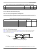
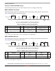
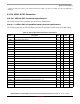
The following figure depicts the transmit timing of UART in the RS-232 serial mode, with 8 data bit/1
stop bit format. Table 91 lists the UART RS-232 serial mode transmit timing characteristics.
Figure 53. UART RS-232 Serial Mode Transmit Timing Diagram
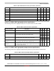
4.10.15.0.2 UART Receiver
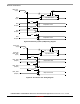
The following figure depicts the RS-232 serial mode receive timing with 8 data bit/1 stop bit format.
Table 92 lists serial mode receive timing characteristics.
Figure 54. UART RS-232 Serial Mode Receive Timing Diagram
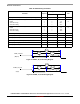
Table 91. UART RS-232 Serial Mode Transmit Timing Parameters
ID Parameter Symbol Min Max Unit
UA1 Transmit Bit Time t
Tbit
1/F
baud_rate
1
– T
ref_clk
2
1
F
baud_rate
: Baud rate frequency. The maximum baud rate the UART can support is (LPUART_clk frequency)/(SBR[12:0]
× (OSR+1)).
2
T
ref_clk
: The period of UART reference clock ref_clk (LPUART_clk after SBR divider).
1/F
baud_rate
+ T
ref_clk
—
Table 92. RS-232 Serial Mode Receive Timing Parameters
ID Parameter Symbol Min Max Unit
UA2 Receive Bit Time
1
1
The UART receiver can tolerate 1/((OSR+1) × Fbaud_rate) tolerance in each bit, but accumulation tolerance in one frame must
not exceed 3/((OSR+1) × Fbaud_rate).
t
Rbit
1/F
baud_rate
2
–
1/(16 × F
baud_rate
)
2
F
baud_rate
: Baud rate frequency. The maximum baud rate the UART can support is (LPUART_clk frequency)/(SBR[12:0] ×
(OSR+1)).
1/F
baud_rate
+
1/(16 × F
baud_rate
)
—
Bit 1 Bit 2Bit 0 Bit 4 Bit 5 Bit 6
Bit 7
UARTx_TX_DATA
(output)
Bit 3
Start
Bit
STOP
BIT
NEXT
START
BIT
POSSIBLE
PAR ITY
BIT
Par Bit
UA1
UA1
UA1
UA1
Bit 1 Bit 2Bit 0 Bit 4 Bit 5 Bit 6
Bit 7
UARTx_RX_DATA
(input)
Bit 3
Start
Bit
STOP
BIT
NEXT
START
BIT
POSSIBLE
PAR ITY
BIT
Par Bit
UA2
UA2
UA2
UA2