
Datasheet


Electrical characteristics
i.MX 8QuadXPlus and 8DualXPlus Automotive and Infotainment Applications Processors, Rev. 0, 11/2018
PRELIMINARYNXP Semiconductors 57
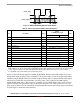
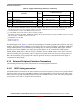
Below are the LPSPI interfaces and their respective chip selects:
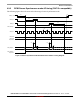
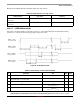
4.10.1.1 LPSPI Master mode
Waveform is assuming LPSPI is configured in mode 0, i.e. TCR.CPOL=0b0 and TCR.CPHA=0b0. Timing
parameters are valid for all modes using appropriate edge of the clock.
Figure 20. LPSPI Master mode
Table 48. LPSPI interfaces and chip selects
LPSPI interface Chip select Comment
60 MHz in Master mode and 40 MHz in
Slave mode
SPI0, SPI2, SPI2b, SPI3
40 MHz in Master mode and 20 MHz in
Slave mode
SPI1, SPI1b, SPI2c+ —
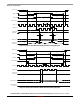
Table 49. LPSPI timings—Master mode at 60 MHz
ID Parameter Min Max Unit
— SPIx_SCLK Cycle frequency — 60 MHz
t1 SPIx_SCLK High or Low Time–Read
SPIx_SCLK High or Low Time–Write
7.5 — ns
t2 SPIx_CSy pulse width 7.5 — ns
t3 SPIx_CSy Lead Time
(1)
FCLK_PERIOD
(2)
x (PCSSCK
+ 1) / 2
PRESCALE
- 3
—ns
t4 SPIx_CSy Lag Time
(3)
FCLK_PERIOD
(2)
x (SCKPCS
+ 1) / 2
PRESCALE
+ 3
—ns