
Datasheet


Electrical characteristics
i.MX 8QuadXPlus and 8DualXPlus Automotive and Infotainment Applications Processors, Rev. 0, 11/2018
PRELIMINARY NXP Semiconductors28
4.3.2 PLLs dedicated to specific interfaces
The following sections cover PLLs used for specific interfaces. Clock output frequency and clock output
range refer to the output of the PLL. Additional clock dividers may be on the output path to divide the
output frequency down to the targeted frequency. See the related sections in the reference manual for
settings of these clock dividers.
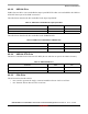
4.3.2.1 Ethernet PLL
This PLL is controlled by the SCU.
4.3.2.2 MLB PLL
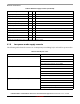
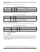
MIPI-DSI Subsystem 24 650 1300 864 MHz
MIPI-CSI Subsystem 24 650 1300 720 MHz
SCU (System
Controller Unit)
Subsystem 24 650 1300 1056 MHz
1
Operating frequencies are limited to only those supported by the SCFW.
2
1200 MHz is used to generate the max frequency points, and 1000 MHz for the typical frequency point. See Table 6 to get
associated voltages.
3
700 MHz is used to generate the max frequency point, and 744 is used to generate the typical point (372 MHz).
4
850 MHz is used to generate the max frequency point, and 744 is used to generate the typical point (372 MHz)
5
2400 MHz is used to generate 1200 MHz when in LPDDR4 mode. 1866 MHz is used to generate 933 MHz when in DDR3L
mode. See Ta bl e 6 to get associated voltages.
Table 15. Ethernet PLL
Parameter Value Unit
Reference clock 24 MHz
Clock output frequency 1 GHz
Table 16. MLB PLL
Parameter Value Unit Comments
Reference clock ≤100 MHz From differential input clock pads
Clock output frequency ≤400 MHz
—
Table 14. PLLs controlled by SCU (continued)
Subsystem PLL usage Source clock
Locking range
1
Lock freq. Unit
Min freq. Max freq.