
Datasheet


Electrical characteristics
i.MX 8QuadXPlus and 8DualXPlus Automotive and Infotainment Applications Processors, Rev. 0, 11/2018
PRELIMINARYNXP Semiconductors 25
4.2 Power supplies requirements and restrictions
The system design must comply with power-up sequence, power-down sequence, and steady state
guidelines as described in this section to ensure the reliable operation of the device. Any deviation from
these sequences may result in the following situations:
• Excessive current during power-up phase
• Prevention of the device from booting
• Irreversible damage to the processor
4.2.1 Power-up sequence
The device has the following power-up sequence requirements:
• Supply group 0 (SNVS) must be powered first. It is expected that group 0 will typically remain
always on after the first power-on.
• Supply group 1 (MAIN and SCU) and group 0 must both be powered to their nominal values prior
to boot. They must power up after or simultaneously with group 0.
• Supply group 2 (I/O’s and DDR interface) consists of those modules required to start the boot
process by accessing external storage devices. These must be fully powered prior to POR release
if booting from one of these supplies interfaces. They must power up after or simultaneously with
group 1.
• Supply group 3 consists of the remaining portions of the SoC. This includes nonboot I/O voltages
and supplies for the major computational units. These can be sequenced in any order and as
required to perform the desired functions for the intended application.
4.2.2 Power-down sequence
The device processor has the following power-up sequence requirements:
•
Supply group 0 must be turned off last, after all other supplies.
• Supply group 1 can be turned off just prior to group 0.
All remaining supplies can be turned off prior to group 1.
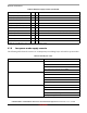
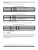
4.2.3 Power Supplies Usage
The following table shows the power supplies usage by group.