
Datasheet


Electrical characteristics
i.MX 8QuadXPlus and 8DualXPlus Automotive and Infotainment Applications Processors, Rev. 0, 11/2018
PRELIMINARY NXP Semiconductors14
4 Electrical characteristics
This section provides the device and module-level electrical characteristics for these processors.
4.1 Chip-level conditions
This section provides the device-level electrical characteristics for the SoC. See the following table for a
quick reference to the individual tables and sections.
4.1.1 Absolute Maximum Ratings
CAUTION
Stresses beyond those listed under Table 4 may affect reliability or cause
permanent damage to the device. These are stress ratings only. Functional
operation of the device at these or any other conditions beyond those
indicated in the “Operating ranges” or other parameter tables is not implied.
Exposure to absolute-maximum-rated conditions for extended periods will
affect device reliability.
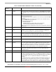
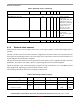
Table 3. Chip-level conditions
For these characteristics, … Topic appears …
Absolute maximum ratings on page 14
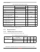
FCPBGA package thermal resistance data on page 16
Operating ranges on page 17
External Input Clock Frequency on page 20
Maximum supply currents on page 21
USB 2.0 PHY typical current consumption in Power-Down
Mode
on page 24
USB 3.0 PHY typical current consumption in Power-Down
Mode
on page 24
Typical current consumption in Power-Down mode for USB
2.0 PHY embedded in USB 3.0 PHY
on page 24
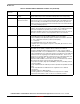
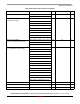
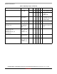
Table 4. Absolute maximum ratings
Parameter Description Symbol Min Max Units
Core Supplies Input Voltage VDD_A35 -0.3 1.2 V
VDD_GPU
VDD_MAIN
DDR PHY supplies VDD_DDR_VDDQ -0.3 1.75 V