
Datasheet


Boot mode configuration
i.MX 8QuadXPlus and 8DualXPlus Automotive and Infotainment Applications Processors, Rev. 0, 11/2018
PRELIMINARYNXP Semiconductors 107
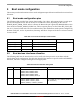
5 Boot mode configuration
This section provides information on boot mode configuration pins allocation and boot devices interfaces
allocation.
5.1 Boot mode configuration pins
The following table provides boot options, functionality, fuse values, and associated pins. Several input
pins are also sampled at reset and can be used to override fuse values, depending on the value of
FORCE_BOOT_FROM_FUSE. After it is blown, the Boot mode pin is ignored by ROM; ROM receives
'boot mode' from the BT_MODE_FUSES fuse. The boot option pins are in effect when BT_FUSE_SEL
fuse is ‘0’ (cleared, which is the case for an unblown fuse). For detailed boot mode options configured by
the Boot mode pins, see the “System Boot, Fusemap, and eFuse” chapter of the device reference manual
for more details.
5.2 Boot devices interfaces allocation
The following table lists the interfaces that can be used by the boot process in accordance with the
specific Boot mode configuration. The table also describes the interface’s specific modes and IOMUXC
allocation, which are configured during boot when appropriate.
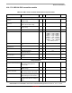
Table 108. Fuse and associated pins used for Boot
Interface IP Instance Allocated Pads During Boot Comment
BOOT_MODE[0] Input SCU_BOOT_MODE0 Boot mode selection
BOOT_MODE[1] Input SCU_BOOT_MODE1
BOOT_MODE[2] Input SCU_BOOT_MODE2
BOOT_MODE[3] Input SCU_BOOT_MODE3
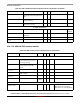
Table 109. Interface allocation during boot
Interface IP Instance Allocated Pads During Boot Comment
eMMC USDHC0 EMMC0_CLK, EMMC0_CMD, EMMC0_DATA0,
EMMC0_DATA1, EMMC0_DATA2,
EMMC0_DATA3, EMMC0_DATA4,
EMMC0_DATA5, EMMC0_DATA6,
EMMC0_DATA7, EMMC0_RESET_B
SD USDHC1 USDHC1_CD_B, USDHC1_CLK, USDHC1_CMD,
USDHC1_DATA0, USDHC1_DATA1,
USDHC1_DATA2, USDHC1_DATA3,
USDHC1_RESET_B, USDHC1_VSELECT
USDHC1_CD_B is used by first (A0) silicon only.
Second (B0) silicon uses USDHC1_DATA3 for
CD (Card Detect).