
Datasheet


Electrical characteristics
i.MX 8QuadXPlus and 8DualXPlus Automotive and Infotainment Applications Processors, Rev. 0, 11/2018
PRELIMINARY NXP Semiconductors102
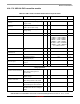
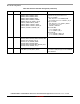
4.10.17.3 USB 3.0 PHY receiver module
T
TX-IDLE-TO-DIFF-DATA
Maximum time to transition to valid
diff signaling after leaving Electrical
Idle
—— 8 ns
V
TX-CM-AC-PP
Tx AC peak-peak common mode
voltage (5.0 GT/s)
20 — 150 mVpp
T
EIExit
Time to exit Electrical Idle (L0s)
state and to enter L0
— — 5 Txsysclk
Tx signal characteristics
f
tol
TX Frequency Long Term Accuracy -300 — 300 ppm of
Fbaud
f
SSC
Spread-Spectrum Modulation
Frequency
30 — 33 kHz
t
20-80TX
TX Rise/Fall Time 0.2 — 0.41 UI
t
skewTX
TX Differential Skew — — 20 ps
1
For USB 3.0, no EQ is required
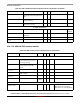
Table 104. USB 3.0 PHY receiver module electrical specifications
Symbol Description Min Typ Max Unit Comments
Voltage Param eters
V
RX-DIFF(p-p)
Differential input voltage
(peak-to-peak) (that is, receiver
eye voltage opening)
100 — 1200 mV —
V
RX-IDLE-DET-DIFF(p-p)
Differential input threshold voltage
(peak-to-peak) to detect idle
(LFPS)
100 — 300 mV USB3 LFPS
V
cm, acRX
RX AC Common Mode Voltage — — 100 mVp-p Simulated at 250 MHz
V
RX-CM-AC
Receiver common-mode voltage
for AC coupling
—0150mV —
Z
RX-DIFF-DC
Differential input impedance (DC) 80 100 120 W 100 Ω ± 10%
RL
RX-DIFF
Receiver differential return loss Same as
TX RL
—— dB —
Jitter Parameters
T
RX-MAX-JITTER
Receiver total jitter tolerance 0 — 0.66 UI Incoming Jitter:
USB3 = 0.43UI DJ + 0.23UI RJ
USB3 numbers are with REFC-TLE
Table 103. USB 3.0 PHY transmitter module electrical specifications (continued)
Symbol Description Min Typ Max Unit