
Datasheet


Electrical characteristics
i.MX 8QuadXPlus and 8DualXPlus Automotive and Infotainment Applications Processors, Rev. 0, 11/2018
PRELIMINARYNXP Semiconductors 101
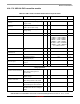
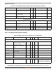
4.10.17.2 USB 3.0 PHY transmitter module
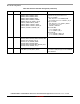
Table 103. USB 3.0 PHY transmitter module electrical specifications
Symbol Description Min Typ Max Unit
Voltage/current parameters
V
TX-DIFFp
Programmable output voltage swing
(single-ended)
50 — 500 mV
V
TX-DIFFp-p
Programmable differential
peak-to-peak output voltage
100 — 1000 mV
V
TX-DIFFp-p-LOW
1
Low power differential p-p TX
voltage swing
400 — 1200 mV
I
TX-SHORT
Transmit lane short-circuit current — — 100 mA
RL
TX-DIFF
Transmitter differential return loss — — 0 < -20dB < 100Mhz
100Mhz < -18dB < 300Mhz
300Mhz < -16dB < 600Mhz
600Mhz < -10dB < 2500Mhz
2500Mhz < -9dB < 4875Mhz
4875Mhz < -8dB < 11200Mhz
11200Mhz < -5dB < 16800Mhz
and -3dB beyond that
Db
RL
TX-CM
Transmitter common mode return
loss
— — 50Hz < -8dB < 15000Mhz dB
Z
TX-DIFF-DC
DC differential TX impedance 80 100 120 Ω
UI Unit Interval 199.94 — 200.06 ps
T
TX-MAX-JITTER
Transmitter total jitter
(peak-to-peak) (T
j
)
—— 0.4 UI
T
TX-RJ-PLL-sigma
After application of TX jitter transfer
function
— — 2.42 ps
LTLAT-10 Transmitter data latency — — 210 UI
Voltage para m ete rs
V
TX-CM-DC-ACTIVE-IDLE-DELTA
Absolute Delta of DC Common
Mode Voltage during L0 and
Electrical Idle.
0— 100 mV
V
TX-IDLE-DIFF-AC-p
Electrical Idle Differential Peak
Output Voltage
0— 20 mV
V
TX-CM-DC-LINE-DELTA
Absolute Delta of DC Common
Mode Voltage between D+ and D-
0— 25 mV
V
TX-RCV-DETECT
The amount of voltage change
allowed during Receiver Detection
0— 600 mV
T
TX-IDLE-SET-TO-IDLE
Maximum time to transition to a
valid Electrical Idle after sending an
EIOS
—— 8 ns