
Datasheet


Electrical characteristics
i.MX 8QuadXPlus and 8DualXPlus Automotive and Infotainment Applications Processors, Rev. 0, 11/2018
PRELIMINARY NXP Semiconductors100
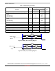
4.10.16.4 USB 2.0 PHY full-speed/high-speed terminations specification
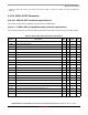
The following table lists the full-speed/low-speed (FS/LS) Terminations Specification of USB 2.0 PHY.
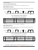
4.10.16.5 Voltage threshold specification
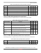
The following table lists the OTG Comparator Specifications of USB2.0 PHY.
4.10.17 USB 3.0 PHY parameters
The following content is from the USB 3.0 PHY specifications.
4.10.17.1 USB 3.0 PHY external component
Table 100. USB 2.0 PHY FS/LS terminations specification
Symbol Description Min Typ Max Units
RPU Bus Pull-Up resistor on US Port in IDLE State 900 — 1575 Ω
Bus Pull-Up resistor on US Port in ACTIVE State 1425 — 3090 Ω
RPD Bus Pull-Down resistor on DS Port 14.25 — 24.8 KΩ
VTERM Termination Voltage for US Port Pull-Up (RPU) 3.0 — 3.6 V
Table 101. USB 2.0 PHY OTG comparator specifications
1
1
USB 2.0 PHY features embedded 3.3 V ESD protection on VBUS port. As a consequence, there are two options of applying
the VBUS signal to PHY: either directly, when VBUS level is limited to 3.3 V, or indirectly through the external voltage divider.
The threshold values specified in the above table refer to the case when neither ESD protection nor external divider is present.
Symbol Description Min Typ Max Units
sessvld B-Device Session Valid threshold 0.8 — 4.0 V
vbusvalid VBUS Valid threshold 4.4 — 4.75 V
Table 102. USB 3.0 PHY external component specifications
Name Min Typ Max Units Descriptions
rext 497.5 500 502.5 Ω There needs to be an external resistor component connected at rext ball while the
internal resistor or current is getting calibrated. Package routing from rext ball to its
respective bump should not contribute more than 0.05 Ω.