
User guide

12 DSPAUDIOEVM Evaluation Board Users Manual MOTOROLA
This document contains information on a new product. Specifications and information herein are subject to change without notice.
SECTION 3 DAUGHTERBOARD
3.1 DSPX36XDB1
These daughterboard connection and jumper definitions are specific to the DSPX36XDB1 boards. Any
future alternate daughterboards will have additional documentation.
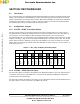
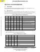
3.2 Mode Selection
Various boot-up modes can be selected via the MODE pins and pins PB13 and PB14 settings can be determined
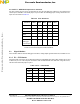
using switch bank SW1. Switch position “ON”= signal high. Table 13 shows the modes available for the 56362/
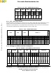
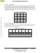
366/367. Table 14 shows the modes available for 56364. See part-specific user manual for full details.
* These modes are only applicable to DSPs which have the embedded ROM based Software
Architecture (SA).
Note: All other modes are reserved and should not be used.
Table 3.1 Mode Selection for 56362/366/367
MODD MODC MODB MODA PB14* PB13* Mode
0 0 0 0 X X Expanded mode (execute from $C00000)
0 0 0 1 X X Bootstrap from external FLASH
0 0 1 0 0 1 Bootstrap SA in SPI mode*
0 0 1 0 1 1
Bootstrap SA in I
2
C mode*
0 1 0 1 X X Boot from SHI (slave SPI mode)
0 1 1 1 X X
Boot from SHI (slave I
2
C mode)
1 0 0 0 X X Expanded mode (execute from $008000)
1 1 0 0 X X Bootstrap in HDI08 ISA mode
1 1 0 1 X X Bootstrap in HDI08 HC11 mode
1 1 1 0 X X Bootstrap in HDI08 8051 mode
1 1 1 1 X X Bootstrap in HDI08 69302 mode
Table 3.2 Mode Selection for 56364
MODD MODC MODB MODA Mode
0 X 0 0 Jump to PROM starting address
0 X 0 1 Bootstrap from byte-wide memory
0 X 1 0 Reserved
0 X 1 1 Reserved for Burn-in testing
1 X 0 0 Reserved
1 X 0 1 Bootstrap from SHI (slave SPI mode)
1 X 1 0 Bootstrap from SHI (slave I2C mode, clock freeze
enabled)
1 X 1 1 Bootstrap from SHI (slave I2C mode, clock freeze disabled
Frees
cale Semiconductor,
I
Freescale Semiconductor, Inc.
For More Information On This Product,
Go to: www.freescale.com
nc...