
User guide

MOTOROLA DSPAUDIOEVM Evaluation Board Users Manual 11
This document contains information on a new product. Specifications and information herein are subject to change without notice.
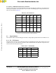
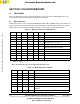
If using the Software Architecture, the analog outputs correspond to the following:
AOUT1 WHITE Left Main
AOUT1 RED Right Main
AOUT2 WHITE Left Surround
AOUT2 RED Right Surround
AOUT3 WHITE Center
AOUT3 RED Subwoofer
AOUT4 WHITE Left Back
AOUT4 RED Right Back
AOUT5 WHITE Left Secondary
AOUT5 RED Right Secondary
AOUT6 WHITE Unassigned
AOUT6 RED Unassigned
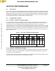
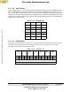
2.5.3 J13 — Headphone Outputs
These channels can also be monitored with the on-board headphone amplifier. The channel listened to is
selected via switches SW2 and SW3. Moving the switch to the right will enable the corresponding channel.
There are right and left volume sliders (RV3 and RV4) to allow variations in volume level and balance
control. Headphones should be plugged in to the J13 1/8-inch headphone connector.
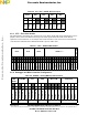
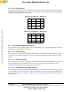
2.5.3.1 SW2 / SW3 — Channel Select
These switches control what is routed to the on-board headphone amplifier. Moving the switch to the right
will enable the corresponding channel. Multiple switches/channels can be enabled at one time, and the
signals will be summed into the the corresponding headphone channel.
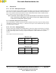
2.5.3.2 RV3 / RV4 — Headphone Volume Select
These sliders allow for volume and balance adjustment for the headphone amplifier. To help prevent
damage to headphones or hearing, always start with the sliders in a low-volume position.
Frees
cale Semiconductor,
I
Freescale Semiconductor, Inc.
For More Information On This Product,
Go to: www.freescale.com
nc...