
User guide

10 DSPAUDIOEVM Evaluation Board Users Manual MOTOROLA
This document contains information on a new product. Specifications and information herein are subject to change without notice.
2.5 External I/O
2.5.1 J9 / J10 — Microphone Inputs
There are two microphone inputs available at 1/8inch microphone connectors J9 and J10 labeled MIC1 and
MIC2. These can also be monitored via headphones by switching MIC1 and MIC2 on. The input levels of
these can be adjusted with the potentiometers at RV1 and RV2 labeled MIC1 LEVEL and MIC2 LEVEL.
These signals are connected to the ADC2 A/D converter.
Note: If 1/4 inch to 1/8 inch adaptors are used for the microphone connection use only stereo-
stereo or mono-mono style adapters. Stereo-mono or mono-stereo adapters will result in
a short of the incoming audio signal to ground.
2.5.1.1 RV1/RV2 - Microphone Gain Control
These potentiometers control the input levels for MIC1 and MIC2 respectively. To prevent damage, always
start with these controls in a low setting, i.e., twisted left. These inputs can be monitored directly, using the
on-board headphone amplifier.
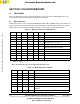
2.5.2 J11 / J12 — Analog Outputs
Fixed pre-amp outputs (Variable through Digital Volume control on the DSP) are provided for 12 channels
of output. These RCA connections can be fed into a variable or fixed amplifier stage. Care should be taken
to verify signal integrity before connecting to large fixed amplifiers to avoid audible noise or speaker
damage.
These outputs are located at J11 and J12.
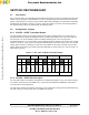
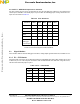
Table 2.11 J11
AOUT1 AOUT2 AOUT3
White White White
Red Red Red
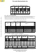
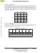
Table 2.12 J12
AOUT4 AOUT5 AOUT6
White White White
Red Red Red
Frees
cale Semiconductor,
I
Freescale Semiconductor, Inc.
For More Information On This Product,
Go to: www.freescale.com
nc...