
User guide

MOTOROLA DSPAUDIOEVM Evaluation Board Users Manual 9
This document contains information on a new product. Specifications and information herein are subject to change without notice.
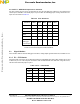
2.3.4 TP1 / TP2 Headers
TP1 and TP2 jumper blocks route to daughterboard for GPIO test points and future flexibility. On the DSP
56362/6/7 parts, as an example, these headers are connected to the DSP HDI08 port. See daughterboard
schematics and appendix for device specifics.
2.4 On-board Debugger Connections
The connectors discussed in this section are the on-board debuggers. For specific information on using the
debuggers, see the relevant User’s Manuals.
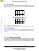
2.4.1 J2 — USB Interface
This connector is used in conjunction with the SDI software to debug a DSP using USB communications.
See Section 2.2.4 Debugger and Microcontroller Configuration for the proper jumper settings to use this
interface.
2.4.2 J3 — RS232 Interface
This connector can be used for debugging or for in-field updating of the microcontroller code. To use this
port for debugging, the SDI software must be used. See Section 2.2.4 Debugger and Microcontroller
Configuration for the proper jumper settings to use this interface.
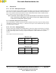
2.4.3 J4 — Parallel Port Debugger Interface
This connector is used for the on-board Suite56 Parallel Port Command Converter. In conjunction with the
Suite56 software, this interface provides a high-speed debugger connection through the JTAG/OnCE port
of the DSP. See Section 2.2.4 Debugger and Microcontroller Configuration for the proper jumper settings to
use this interface.
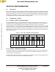
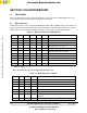
Table 2.9 TP1 Header — GP TP1–8
TP1 * * TP8
TP2 * * TP7
TP3 * * TP6
TP4 * * TP5
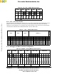
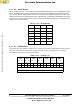
Table 2.10 TP2 Header — GP TP9–16
TP9 * * TP16
TP10 * * TP15
TP11 * * TP14
TP12 * * TP13
Frees
cale Semiconductor,
I
Freescale Semiconductor, Inc.
For More Information On This Product,
Go to: www.freescale.com
nc...