
User guide

MOTOROLA DSPAUDIOEVM Evaluation Board Users Manual 7
This document contains information on a new product. Specifications and information herein are subject to change without notice.
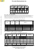
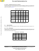
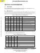
2.2.4.6 JP11 – AUX Mode Input Source Selection
The JP11 jumpers are present as an alternative to using the SDI debugger software to select between the
various inputs available. If the AUX5 jumper is present then the following jumper settings will result in the
input selection shown in Table 2.5
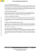
2.3 Signal Headers
These headers allow for external debugger connections, analog output signal measurement, and GPIO access.
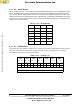
2.3.1 P1 — PPI Header
The PPI header connections are to allow for backwards compatibility with existing PPI software tool set and
to allow easy access to the SHI port connections from the motherboard. Note that when using PPI source,
JP8 must have PPI Port jumper in place.
Table 2.5 JP11 Selections
Input
Selected
Aux5 Aux4* Aux3 Aux2 Aux1
RX1
1 0 0 0 0
RX2
1 0 0 0 1
RX3
1 0 0 1 0
RX4
1 0 0 1 1
AIN1
1 0 1 0 0
SDI
debugger
selects input
0 X X X X
* When the Aux5 jumper is present, the Aux4 jumper directly
controls the mute functionality of the EVM motherboard.
Table 2.6 P1 — PPI Header
NC(1) * * SS/HA2
GND * * SCK/SCL
GND * * HREQ
SDA * * MOSI / HA0
VDD * * MISO
Frees
cale Semiconductor,
I
Freescale Semiconductor, Inc.
For More Information On This Product,
Go to: www.freescale.com
nc...