
User guide

6 DSPAUDIOEVM Evaluation Board Users Manual MOTOROLA
This document contains information on a new product. Specifications and information herein are subject to change without notice.
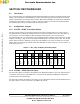
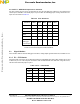
2.2.4.1 PJ6 Debug MPU Crystal Selection
The JP6 jumper is for selection of RS232 or USB communication when using the SDI debugger. Note that
USB mode is not possible when using the Win NT software version. The RS232 position should be jumpered
when the RS232 interface is used for the SDI debugger, and the USB/PGM position should be used when
using the USB interface for the SDI debugger or when reprogramming of the Debug Micro is required. Only
one of these jumpers should be connected at any one time. Use of the wrong jumper setting will cause SDI
communication failure to occur or a reduction in the data transfer rate.
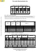
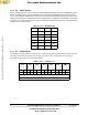
2.2.4.2 JP7 – MPU Program Control
The JP7 jumpers are only used when the on-board microcontrollers are to be re-programmed. Placing a
jumper in the PGM position places the selected microcontroller in program mode upon power-on. The
microcontroller to be programmed is selected by placing a jumper in either the DEBUG MPU or CONFIG
MPU positions. With no jumper in the PGM position, the other two jumpers are ignored.
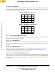
2.2.4.3 JP8 – SHI Debug Source Selection
The JP8 jumpers are for selection of various debugger modes. The default selection is for SDI debugger
use. The PPI port can be used with legacy "PPP Development Interface" software and a PPI cable although
the latest SDI debugger software is the preferred option for future upgradability and support. The third
option, CONFIG MPU, is not currently supported on the EVM. Only one jumper position should be used at
any one time.
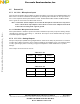
2.2.4.4 JP9 – OnCE/JTAG Debugger Source Selection
The JP9 jumpers are used for selection of alternative debugging tools such as the Suite 56 OnCE interface
mentioned earlier. To use this, simply connect to a host PC with a parallel cable and have a jumper in the
PARALLEL positions. The OnCE jumper option can be used if the user wishes to connect an external OnCE/
JTAG debugger interface to the board. The USB/RS232 option is not currently supported and only one
jumper should be inserted at a time.
2.2.4.5 JP10 – Config / Debug MPU Communication
The JP10 jumpers provide a communication port between the debug microcontroller and the configuration
microcontroller. When the SDI debugger is used and the AUX5 jumper is out, the SDI debugger interface
controls the audio input source. The JP10 jumpers provide a communication port between the debug
microcontroller and the configuration microcontroller. When the SDI debugger is used, and the AUX5 jumper
is out, the SDI debugger interface controls the audio input source. To allow this, all JP10 jumpers should be
populated.
Frees
cale Semiconductor,
I
Freescale Semiconductor, Inc.
For More Information On This Product,
Go to: www.freescale.com
nc...