
User guide

MOTOROLA DSPAUDIOEVM Evaluation Board Users Manual 5
This document contains information on a new product. Specifications and information herein are subject to change without notice.
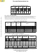
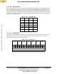
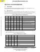
2.2.3 JP5 — Pass-thru Header
This jumper block is included to give convenient access to all the critical audio clocks and data lines. These
jumpers can be removed to allow for rerouting of the audio signals within the board and to allow for
expansion to external boards. As an example, this header could be used to connect to an external audio
codec board for evaluation of the Motorola DSP with a specific audio codec.
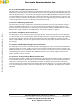
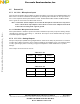
2.2.4 Debugger and Microcontroller Configuration
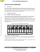
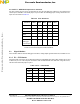
Table 2.2 JP3 / JP4 – S/PDIF Receiver Input
IN=HI RX1 RX2 RX3 RX4
* * * * * * * * * *
* * * * * * * * * *
DIF2
DIF0
DSP
4114
DSP
4114
DSP
4114
DSP
4114
JP3 JP4
Table 2.3 JP5 — PASS-THRU Header
MCLK BICK LRCLK SERIAL I / O
M
U
T
E
* * * * * * * * * * * * * * * * * * * * * * * * * * * * * * * *
* * * * * * * * * * * * * * * * * * * * * * * * * * * * * * * *
RX01
RX02
TX
ADC
DACA
DACB
RX
TX
ADC
DACA
DACB
RX
TX
ADC
DACA
DACB
RX
ADC1
ADC2
TXS01
DACA1/2
TXS02
DACA3/4
TXSD3
DACA5/6
TXSD4
DACB 1/2
TXSD5
DACB3/4
TXCD6
DACB5/6
MUTE
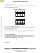
Table 2.4 JP6XXX – Debug MPU Crystal Selection
JB16
EXTAL
PGM MD SHI JTAG MPU COM AUX IN=HI
* * * * * * * * * * * * * * ******
* * * * * * * * * * * * * * ******
RS232
USB/PGM
DEBUG MPU
CONFIG MPU
PGM
PPI PORT
DEBUG MPU
CONFIG MPU
OnCE
USB/RS232
PARALLEL
COM0
COM1
COM2
COM3
AUX1
AUX2
AUX3
AUX4
AUX5
JP6 JP7 JP8 JP9 JP10 JP11
Frees
cale Semiconductor,
I
Freescale Semiconductor, Inc.
For More Information On This Product,
Go to: www.freescale.com
nc...