
Datasheet


September 1993 7
Philips Semiconductors Product specification
Hex inverter 74HCU04
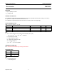
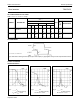
OPTIMUM VALUE FOR R
2
EXTERNAL COMPONENTS FOR RESONATOR
(f < 1 MHz)
Note
1. All values given are typical and must be used as an
initial set-up.
FREQUENCY
(MHz)
R
2
(kΩ)
OPTIMUM FOR
3
2
8
minimum required I
CC
minimum influence due to
change in V
CC
6
1
4.7
minimum I
CC
minimum influence by V
CC
10
0.5
2
minimum I
CC
minimum influence by V
CC
14
0.5
1
minimum I
CC
minimum influence by V
CC
> 14
replace R
2
by C
3
with a typical
value of 35 pF
FREQUENCY
(kHz)
R
1
(MΩ)
R
2
(kΩ)
C
1
(pF)
C
2
(pF)
10 to 15.9 22 220 56 20
16 to 24.9 22 220 56 10
25 to 54.9 22 100 56 10
55 to 129.9 22 100 47 5
130 to 199.9 22 47 47 5
200 to 349.9 10 47 47 5
350 to 600 10 47 47 5
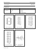
Fig.13 Crystal oscillator configuration.
C
1
= 47 pF (typ.)
C
2
= 33 pF (typ.)
R
1
= 1 to 10 MΩ (typ.)
R
2
optimum value depends on the frequency and required
stability against changes in V
CC
or average minimum I
CC
(I
CC
is typically 5 mA at V
CC
= 5 V and f = 10 MHz).
Note to Application information
All values given are typical unless otherwise specified.
PACKAGE OUTLINES
See
“74HC/HCT/HCU/HCMOS Logic Package Outlines”
.
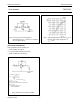
Fig.14 HCU04 used as an astable multivibrator
R
S
≈ 2 × R.
The average I
CC
(mA) is approximately
3.5 + 0.05 × f (MHz) × C (pF) at V
CC
= 5.0 V
(for more information refer to
“DESIGNERS GUIDE”
).
f
1
T
---
1
2.2 RC
------------------
≈=
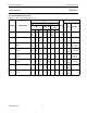
Fig.15 Typical input capacitance as a function of
input voltage.
(1) V
CC
= 2.0 V.
(2) V
CC
= 3.0 V.
(3) V
CC
= 4.0 V.
(4) V
CC
= 5.0 V.
(5) V
CC
= 6.0 V.