
Datasheet


December 1990 14
Philips Semiconductors Product specification
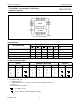
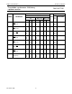
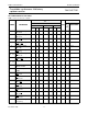
Presettable synchronous 4-bit binary
up/down counter
74HC/HCT191
PACKAGE OUTLINES
See
“74HC/HCT/HCU/HCMOS Logic Package Outlines”
.
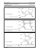
Fig.16 Waveforms showing the set-up and hold times from the parallel load input (PL) to the data input (D
n
).
The shaded areas indicate when the input is
permitted to change for predictable output
performance.
(1) HC : V
M
= 50%; V
I
= GND to V
CC
.
HCT : V
M
= 1.3 V; V
I
= GND to 3 V.
Fig.17 Waveforms showing the set-up and hold times from the count enable and up/down inputs (CE, U/D) to the
clock (CP).
The shaded areas indicate when the input is
permitted to change for predictable output
performance.
(1) HC : V
M
= 50%; V
I
= GND to V
CC
.
HCT : V
M
= 1.3 V; V
I
= GND to 3 V.