
Datasheet
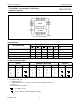


December 1990 13
Philips Semiconductors Product specification
Presettable synchronous 4-bit binary
up/down counter
74HC/HCT191
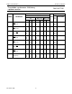
Fig.13 Waveforms showing the input (PL) to output (Q
n
) propagation delays.
(1) HC : V
M
= 50%; V
I
= GND to V
CC
.
HCT : V
M
= 1.3 V; V
I
= GND to 3 V.
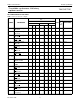
Fig.14 Waveforms showing the up/down count input (U/D) to terminal count and ripple clock output (TC, RC)
propagation delays.
(1) HC : V
M
= 50%; V
I
= GND to V
CC
.
HCT : V
M
= 1.3 V; V
I
= GND to 3 V.
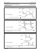
Fig.15 Waveforms showing the parallel load input (PL) pulse width, removal time to clock (CP) and the output
(Q
n
) transition times.
(1) HC : V
M
= 50%; V
I
= GND to V
CC
.
HCT : V
M
= 1.3 V; V
I
= GND to 3 V.