
Datasheet


Table Of Contents
- Section 1. General Description
- 1.1 Contents
- 1.2 Introduction
- 1.3 Features
- 1.3.1 Standard Features of the MC68HC908GP20
- 1.3.2 Features of the CPU08
- 1.4 MCU Block Diagram
- 1.5 Pin Assignments
- 1.6 Pin Functions
- 1.6.1 Power Supply Pins (VDD and VSS)
- 1.6.2 Oscillator Pins (OSC1 and OSC2)
- 1.6.3 External Reset Pin (RST)
- 1.6.4 External Interrupt Pin (IRQ)
- 1.6.5 CGM Power Supply Pins (VDDA and VSSA)
- 1.6.6 External Filter Capacitor Pin (CGMXFC)
- 1.6.7 Analog Power Supply Pins (VDDAD and VSSAD)
- 1.6.8 ADC Voltage Reference High Pin (VREFH)
- 1.6.9 ADC Voltage Reference Low Pin (VREFL)
- 1.6.10 Port A Input/Output (I/O) Pins (PTA7/KBD7-PTA0/KBD0)
- 1.6.11 Port B I/O Pins (PTB7/AD7-PTB0/AD0)
- 1.6.12 Port C I/O Pins (PTC6-PTC0)
- 1.6.13 Port D I/O Pins (PTD7/T2CH1-PTD0/SS)
- 1.6.14 Port E I/O Pins (PTE1/RxD-PTE0/TxD)
- Section 2. Memory Map
- Section 3. Low-Power Modes
- 3.1 Contents
- 3.2 Introduction
- 3.2.1 Wait Mode
- 3.2.2 Stop Mode
- 3.3 Analog-to-Digital Converter (ADC)
- 3.3.1 Wait Mode
- 3.3.2 Stop Mode
- 3.4 Break Module (BRK)
- 3.4.1 Wait Mode
- 3.4.2 Stop Mode
- 3.5 Central Processor Unit (CPU)
- 3.5.1 Wait Mode
- 3.5.2 Stop Mode
- 3.6 Clock Generator Module (CGM)
- 3.6.1 Wait Mode
- 3.6.2 Stop Mode
- 3.7 Computer Operating Properly Module (COP)
- 3.7.1 Wait Mode
- 3.7.2 Stop Mode
- 3.8 External Interrupt Module (IRQ)
- 3.8.1 Wait Mode
- 3.8.2 Stop Mode
- 3.9 Keyboard Interrupt Module (KBI)
- 3.9.1 Wait Mode
- 3.9.2 Stop Mode
- 3.10 Low-Voltage Inhibit Module (LVI)
- 3.10.1 Wait Mode
- 3.10.2 Stop Mode
- 3.11 Serial Communications Interface Module (SCI)
- 3.11.1 Wait Mode
- 3.11.2 Stop Mode
- 3.12 Serial Peripheral Interface Module (SPI)
- 3.12.1 Wait Mode
- 3.12.2 Stop Mode
- 3.13 Timer Interface Module (TIM1 and TIM2)
- 3.13.1 Wait Mode
- 3.13.2 Stop Mode
- 3.14 Timebase Module (TBM)
- 3.14.1 Wait Mode
- 3.14.2 Stop Mode
- 3.15 Exiting Wait Mode
- 3.16 Exiting Stop Mode
- Section 4. Resets and Interrupts
- Section 5. Analog-to-Digital Converter (ADC)
- 5.1 Contents
- 5.2 Introduction
- 5.3 Features
- 5.4 Functional Description
- 5.4.1 ADC Port I/O Pins
- 5.4.2 Voltage Conversion
- 5.4.3 Conversion Time
- 5.4.4 Conversion
- 5.4.5 Accuracy and Precision
- 5.5 Interrupts
- 5.6 Low-Power Modes
- 5.6.1 Wait Mode
- 5.6.2 Stop Mode
- 5.7 I/O Signals
- 5.7.1 ADC Analog Power Pin (VDDAD)/ADC Voltage Reference High Pin (VREFH)
- 5.7.2 ADC Analog Ground Pin (VSSAD)/ADC Voltage Reference Low Pin (VREFL)
- 5.7.3 ADC Voltage In (ADVIN)
- 5.8 I/O Registers
- 5.8.1 ADC Status and Control Register
- 5.8.2 ADC Data Register
- 5.8.3 ADC Clock Register
- Section 6. Break Module (BRK)
- 6.1 Contents
- 6.2 Introduction
- 6.3 Features
- 6.4 Functional Description
- 6.4.1 Flag Protection During Break Interrupts
- 6.4.2 CPU During Break Interrupts
- 6.4.3 TIMI and TIM2 During Break Interrupts
- 6.4.4 COP During Break Interrupts
- 6.5 Low-Power Modes
- 6.5.1 Wait Mode
- 6.5.2 Stop Mode
- 6.6 Break Module Registers
- 6.6.1 Break Status and Control Register
- 6.6.2 Break Address Registers
- 6.6.3 Break Status Register
- 6.6.4 Break Flag Control Register
- Section 7. Clock Generator Module (CGMC)
- 7.1 Contents
- 7.2 Introduction
- 7.3 Features
- 7.4 Functional Description
- 7.4.1 Crystal Oscillator Circuit
- 7.4.2 Phase-Locked Loop Circuit (PLL)
- 7.4.3 PLL Circuits
- 7.4.4 Acquisition and Tracking Modes
- 7.4.5 Manual and Automatic PLL Bandwidth Modes
- 7.4.6 Programming the PLL
- 7.4.7 Special Programming Exceptions
- 7.4.8 Base Clock Selector Circuit
- 7.4.9 CGMC External Connections
- 7.5 I/O Signals
- 7.5.1 Crystal Amplifier Input Pin (OSC1)
- 7.5.2 Crystal Amplifier Output Pin (OSC2)
- 7.5.3 External Filter Capacitor Pin (CGMXFC)
- 7.5.4 PLL Analog Power Pin (Vdda)
- 7.5.5 PLL Analog Ground Pin (Vssa)
- 7.5.6 Oscillator Enable Signal (SIMOSCEN)
- 7.5.7 Oscillator Stop Mode Enable Bit (OSCSTOPENB)
- 7.5.8 Crystal Output Frequency Signal (CGMXCLK)
- 7.5.9 CGMC Base Clock Output (CGMOUT)
- 7.5.10 CGMC CPU Interrupt (CGMINT)
- 7.6 CGMC Registers
- 7.6.1 PLL Control Register
- 7.6.2 PLL Bandwidth Control Register
- 7.6.3 PLL Multiplier Select Register High
- 7.6.4 PLL Multiplier Select Register Low
- 7.6.5 PLL VCO Range Select Register
- 7.6.6 PLL Reference Divider Select Register
- 7.7 Interrupts
- 7.8 Special Modes
- 7.8.1 Wait Mode
- 7.8.2 Stop Mode
- 7.8.3 CGMC During Break Interrupts
- 7.9 Acquisition/Lock Time Specifications
- 7.9.1 Acquisition/Lock Time Definitions
- 7.9.2 Parametric Influences on Reaction Time
- 7.9.3 Choosing a Filter
- Section 8. Configuration Register (CONFIG)
- Section 9. Computer Operating Properly (COP)
- 9.1 Contents
- 9.2 Introduction
- 9.3 Functional Description
- 9.4 I/O Signals
- 9.4.1 CGMXCLK
- 9.4.2 STOP Instruction
- 9.4.3 COPCTL Write
- 9.4.4 Power-On Reset
- 9.4.5 Internal Reset
- 9.4.6 Reset Vector Fetch
- 9.4.7 COPD (COP Disable)
- 9.4.8 COPRS (COP Rate Select)
- 9.5 COP Control Register
- 9.6 Interrupts
- 9.7 Monitor Mode
- 9.8 Low-Power Modes
- 9.8.1 Wait Mode
- 9.8.2 Stop Mode
- 9.9 COP Module During Break Mode
- Section 10. Central Processor Unit (CPU)
- 10.1 Contents
- 10.2 Introduction
- 10.3 Features
- 10.4 CPU Registers
- 10.4.1 Accumulator
- 10.4.2 Index Register
- 10.4.3 Stack Pointer
- 10.4.4 Program Counter
- 10.4.5 Condition Code Register
- 10.5 Arithmetic/Logic Unit (ALU)
- 10.6 Low-Power Modes
- 10.6.1 Wait Mode
- 10.6.2 Stop Mode
- 10.7 CPU During Break Interrupts
- 10.8 Instruction Set Summary
- 10.9 Opcode Map
- Section 11. FLASH Memory
- 11.1 Contents
- 11.2 Introduction
- 11.3 Functional Description
- 11.4 FLASH Control Register
- 11.5 Charge Pump
- 11.5.1 FLASH Charge Pump Frequency Control
- 11.5.2 Voltage Regulator
- 11.6 FLASH Erase Operation
- 11.7 FLASH Program/Margin Read Operation
- 11.8 FLASH Block Protection
- 11.9 FLASH Block Protect Register
- 11.10 Wait Mode
- 11.11 Stop Mode
- Section 12. External Interrupt (IRQ)
- Section 13. Keyboard Interrupt Module (KBI)
- Section 14. Low-Voltage Inhibit (LVI)
- Section 15. Monitor ROM (MON)
- Section 16. Input/Output (I/O) Ports
- 16.1 Contents
- 16.2 Introduction
- 16.3 Port A
- 16.3.1 Port A Data Register
- 16.3.2 Data Direction Register A
- 16.3.3 Port A Input Pullup Enable Register
- 16.4 Port B
- 16.4.1 Port B Data Register
- 16.4.2 Data Direction Register B
- 16.5 Port C
- 16.5.1 Port C Data Register
- 16.5.2 Data Direction Register C
- 16.5.3 Port C Input Pullup Enable Register
- 16.6 Port D
- 16.6.1 Port D Data Register
- 16.6.2 Data Direction Register D
- 16.6.3 Port D Input Pullup Enable Register
- 16.7 Port E
- 16.7.1 Port E Data Register
- 16.7.2 Data Direction Register E
- Section 17. Random-Access Memory (RAM)
- Section 18. Serial Communications Interface Module (SCI)
- 18.1 Contents
- 18.2 Introduction
- 18.3 Features
- 18.4 Pin Name Conventions
- 18.5 Functional Description
- 18.5.1 Data Format
- 18.5.2 Transmitter
- 18.5.3 Receiver
- 18.6 Low-Power Modes
- 18.6.1 Wait Mode
- 18.6.2 Stop Mode
- 18.7 SCI During Break Module Interrupts
- 18.8 I/O Signals
- 18.8.1 PTE0/TxD (Transmit Data)
- 18.8.2 PTE1/RxD (Receive Data)
- 18.9 I/O Registers
- 18.9.1 SCI Control Register 1
- 18.9.2 SCI Control Register 2
- 18.9.3 SCI Control Register 3
- 18.9.4 SCI Status Register 1
- 18.9.5 SCI Status Register 2
- 18.9.6 SCI Data Register
- 18.9.7 SCI Baud Rate Register
- Section 19. System Integration Module (SIM)
- 19.1 Contents
- 19.2 Introduction
- 19.3 SIM Bus Clock Control and Generation
- 19.3.1 Bus Timing
- 19.3.2 Clock Startup from POR or LVI Reset
- 19.3.3 Clocks in Stop Mode and Wait Mode
- 19.4 Reset and System Initialization
- 19.4.1 External Pin Reset
- 19.4.2 Active Resets from Internal Sources
- 19.5 SIM Counter
- 19.5.1 SIM Counter During Power-On Reset
- 19.5.2 SIM Counter During Stop Mode Recovery
- 19.5.3 SIM Counter and Reset States
- 19.6 Exception Control
- 19.6.1 Interrupts
- 19.6.2 Reset
- 19.6.3 Break Interrupts
- 19.6.4 Status Flag Protection in Break Mode
- 19.7 Low-Power Modes
- 19.7.1 Wait Mode
- 19.7.2 Stop Mode
- 19.8 SIM Registers
- 19.8.1 SIM Break Status Register
- 19.8.2 SIM Reset Status Register
- 19.8.3 SIM Break Flag Control Register
- Section 20. Serial Peripheral Interface Module (SPI)
- 20.1 Contents
- 20.2 Introduction
- 20.3 Features
- 20.4 Pin Name Conventions and I/O Register Addresses
- 20.5 Functional Description
- 20.5.1 Master Mode
- 20.5.2 Slave Mode
- 20.6 Transmission Formats
- 20.6.1 Clock Phase and Polarity Controls
- 20.6.2 Transmission Format When CPHA = 0
- 20.6.3 Transmission Format When CPHA = 1
- 20.6.4 Transmission Initiation Latency
- 20.7 Queuing Transmission Data
- 20.8 Error Conditions
- 20.8.1 Overflow Error
- 20.8.2 Mode Fault Error
- 20.9 Interrupts
- 20.10 Resetting the SPI
- 20.11 Low-Power Modes
- 20.11.1 Wait Mode
- 20.11.2 Stop Mode
- 20.12 SPI During Break Interrupts
- 20.13 I/O Signals
- 20.13.1 MISO (Master In/Slave Out)
- 20.13.2 MOSI (Master Out/Slave In)
- 20.13.3 SPSCK (Serial Clock)
- 20.13.4 SS (Slave Select)
- 20.13.5 CGND (Clock Ground)
- 20.14 I/O Registers
- 20.14.1 SPI Control Register
- 20.14.2 SPI Status and Control Register
- 20.14.3 SPI Data Register
- Section 21. Timebase Module (TBM)
- Section 22. Timer Interface Module (TIM)
- 22.1 Contents
- 22.2 Introduction
- 22.3 Features
- 22.4 Pin Name Conventions
- 22.5 Functional Description
- 22.5.1 TIM Counter Prescaler
- 22.5.2 Input Capture
- 22.5.3 Output Compare
- 22.5.4 Unbuffered Output Compare
- 22.5.5 Buffered Output Compare
- 22.5.6 Pulse Width Modulation (PWM)
- 22.5.7 Unbuffered PWM Signal Generation
- 22.5.8 Buffered PWM Signal Generation
- 22.5.9 PWM Initialization
- 22.6 Interrupts
- 22.7 Low-Power Modes
- 22.7.1 Wait Mode
- 22.7.2 Stop Mode
- 22.8 TIM During Break Interrupts
- 22.9 I/O Signals
- 22.10 I/O Registers
- 22.10.1 TIM Status and Control Register
- 22.10.2 TIM Counter Registers
- 22.10.3 TIM Counter Modulo Registers
- 22.10.4 TIMA Counter Registers
- 22.10.5 TIM Channel Status and Control Registers
- 22.10.6 TIM Channel Registers
- Section 23. Preliminary Electrical Specifications
- 23.1 Contents
- 23.2 Introduction
- 23.3 Absolute Maximum Ratings
- 23.4 Functional Operating Range
- 23.5 Thermal Characteristics
- 23.6 5.0-V DC Electrical Characteristics
- 23.7 3.0-V DC Electrical Characteristics
- 23.8 5.0-V Control Timing
- 23.9 3.0-V Control Timing
- 23.10 Output High-Voltage Characteristics
- 23.11 Output Low-Voltage Characteristics
- 23.12 Typical Supply Currents
- 23.13 ADC Characteristics
- 23.14 5.0-V SPI Characteristics
- 23.15 3.0-V SPI Characteristics
- 23.16 Timer Interface Module Characteristics
- 23.17 Clock Generation Module Characteristics
- 23.17.1 CGM Component Specifications
- 23.17.2 CGM Electrical Specifications
- 23.18 Memory Characteristics
- Section 24. Mechanical Specifications
- Section 25. Ordering Information
Advance Information MC68HC908GP20 — Rev 2.1
378 Freescale Semiconductor
23.2 Introduction
This section contains electrical and timing specifications. These values
are design targets and have not yet been fully tested.
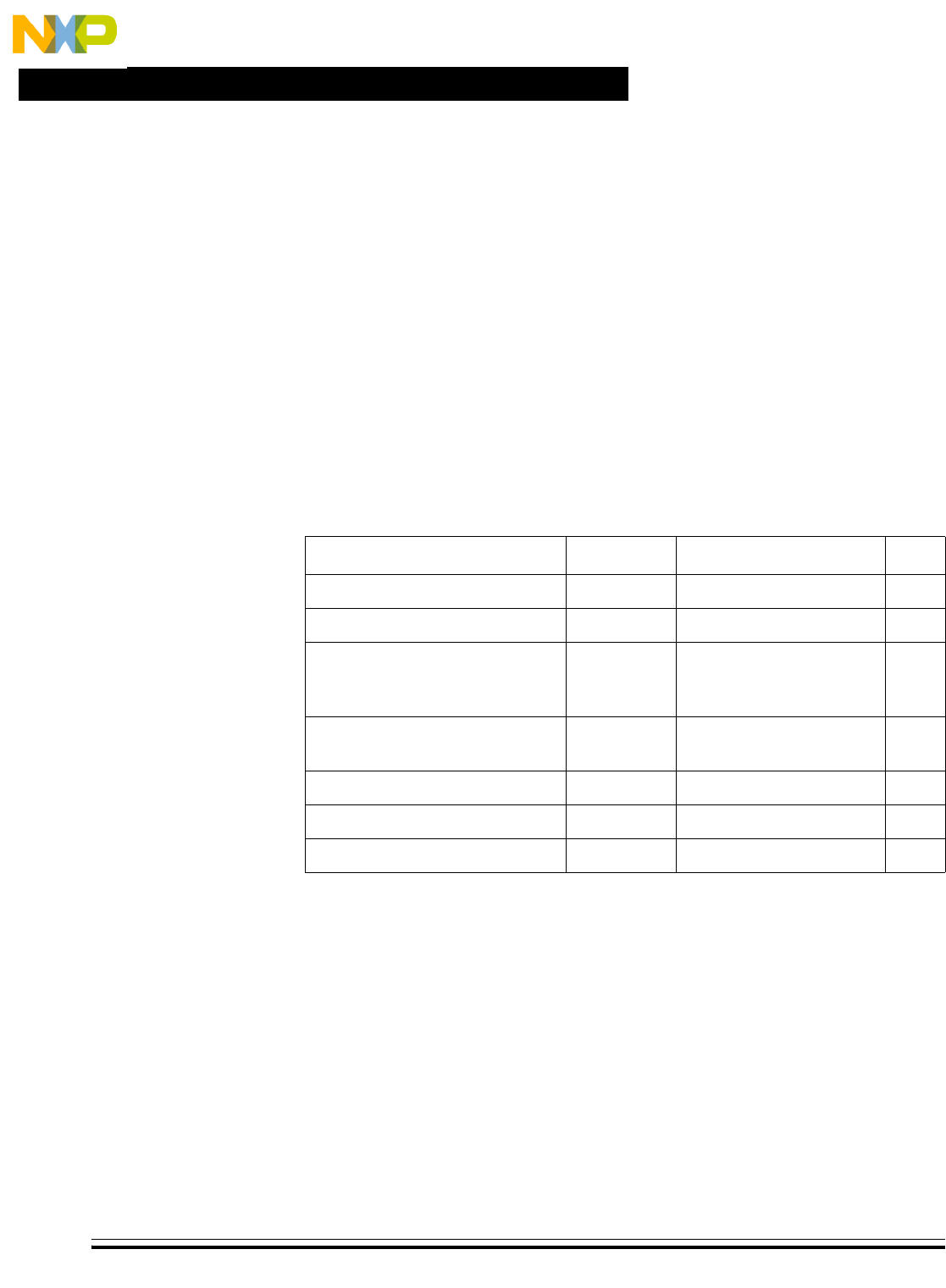
23.3 Absolute Maximum Ratings
Maximum ratings are the extreme limits to which the MCU can be
exposed without permanently damaging it.
NOTE: This device is not guaranteed to operate properly at the maximum
ratings. Refer to 23.6 5.0-V DC Electrical Characteristics for
guaranteed operating conditions.
NOTE: This device contains circuitry to protect the inputs against damage due
to high static voltages or electric fields; however, it is advised that normal
precautions be taken to avoid application of any voltage higher than
maximum-rated voltages to this high-impedance circuit. For proper
operation, it is recommended that V
In
and V
Out
be constrained to the
range V
SS
≤ (V
In
or V
Out
) ≤ V
DD
. Reliability of operation is enhanced if
unused inputs are connected to an appropriate logic voltage level (for
example, either V
SS
or V
DD
).
Characteristic
(1)
1. Voltages referenced to V
SS
Symbol Value Unit
Supply voltage V
DD
–0.3 to + 6.0 V
Input voltage V
In
V
SS
– 0.3 to V
DD
+ 0.3 V
Maximum current per pin
excluding V
DD
, V
SS,
and PTC0–PTC4
I ± 15 mA
Maximum current for pins
PTC0–PTC4
I
PTC0–PTC4
± 25 mA
Maximum current into V
DD
I
mvdd
150 mA
Maximum current out of V
SS
I
mvss
150 mA
Storage temperature T
stg
–55 to +150 °C
Note: