
Datasheet


TDA8025_1 © NXP B.V. 2009. All rights reserved.
Product data sheet Rev. 01 — 6 April 2009 8 of 38
NXP Semiconductors
TDA8025
IC card interface
After powering up the device, pin OFFN remains LOW until pins CMDVCCN and PRES
are both HIGH or pin CMDVCCN is HIGH and pin PRESN is LOW. During power off, pin
OFFN is driven LOW when V
DD(INTREGD)
is below the falling threshold voltage (V
th
).
When pin CMDVCCN is HIGH, the internal oscillator frequency (f
osc(int)
) is switched to Low
frequency (inactive) mode to reduce power consumption.
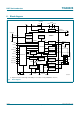
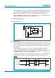
8.2 Voltage supervisors
8.2.1 Block diagram
8.2.2 Description
The voltage supervisors provide both the Power-On Reset (POR) and supply drop-out
detection functions. They control the internal regulated supply voltage (V
DD(INTREGD)
) and
the microcontroller interface supply voltage (V
DD(INTF)
) to ensure problem-free operation of
the TDA8025.
By monitoring both V
DD(INTREGD)
and V
DD(INTF)
, the voltage supervisors ensure these
voltages are high enough to ensure correct operation of the TDA8025 and flawless
communication between it and the microcontroller. This information is combined and sent
to the digital controller in order to reset the TDA8025.
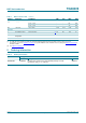
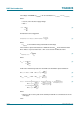
An extension of the power-on reset pulse width of ± 8ms(t
w(POR)
) is used to maintain the
TDA8025 in inactive mode after the supply voltage power on or off sequences (see
Figure 5).
Fig 4. Voltage supervisor circuit
001aai961
REFERENCE
VOLTAGE
V
DD(INTREGD)
V
DD(INTREGD)
V
DD(INTF)
PORADJ
R1
R2
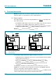
Fig 5. Voltage supervisors V
DD(INTREGD)
and V
DD(INTF)
001aai962
t
w(POR)
t
w(POR)
V
th
+ V
hys
V
th
V
DD(INTREGD)
ALARMN
(internal signal)
Power on Supply dropout Power off