
Datasheet


Table Of Contents
PEMD13_PUMD13 All information provided in this document is subject to legal disclaimers. © NXP B.V. 2011. All rights reserved.
Product data sheet Rev. 3 — 7 December 2011 5 of 16
NXP Semiconductors
PEMD13; PUMD13
NPN/PNP resistor-equipped transistors; R1 = 4.7 k, R2 = 47 k
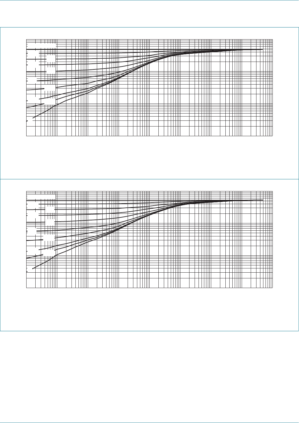
FR4 PCB, standard footprint
Fig 2. Per transistor: Transient thermal impedance from junction to ambient as a function of pulse duration for
PEMD13 (SOT666); typical values
FR4 PCB, standard footprint
Fig 3. Per transistor: Transient thermal impedance from junction to ambient as a function of pulse duration for
PUMD13 (SOT363); typical values
006aac751
10
-5
1010
-2
10
-4
10
2
10
-1
t
p
(s)
10
-3
10
3
1
10
2
10
10
3
Z
th(j-a)
(K/W)
1
duty cycle = 1
0.75
0.5
0.33
0.2
0.1
0.05
0.02
0.01
0
006aac750
10
-5
1010
-2
10
-4
10
2
10
-1
t
p
(s)
10
-3
10
3
1
10
2
10
10
3
Z
th(j-a)
(K/W)
1
duty cycle = 1
0.75
0.5
0.33
0.2
0.1
0.05
0.02
0.01
0