
Datasheet

PCA9670 All information provided in this document is subject to legal disclaimers. © NXP B.V. 2013. All rights reserved.
Product data sheet Rev. 3 — 30 May 2013 32 of 35
NXP Semiconductors
PCA9670
Remote 8-bit I/O expander for Fm+ I
2
C-bus with reset
Modifications:
(continued)
• Section 8.1 “Quasi-bidirectional I/O architecture” re-written
• Section 8.2 “Writing to the port (Output mode)”, first paragraph: first, second and third sentences
re-written
• Figure 13 “Write mode (output)” updated
• Section 8.3 “Reading from a port (Input mode)” re-written
• Figure 14 “Read input port register” updated: label corrected from “data into port” to “data at port”
• Section 8.4 “Power-on reset”: second and third sentences re-written
• Section 8.5 “RESET input”: added new third sentence
• Section 9.3 “Acknowledge”:
– first paragraph: second and third sentences re-written
– second paragraph: third sentence re-written
• Section 10.1 “Bidirectional I/O expander applications”, second paragraph, second sentence changed
from “use the PCA9671” to “use the PCA9672”
• Added Section 10.2 “How to read and write to I/O expander (example)”
• Section 10.3 “High current-drive load applications”:
– first paragraph re-written
– Figure 20 “
High current-drive load application” modified: added resistors on P6 and P7 signals
• Added Section 10.4 “Migration path”
• Table 6 “Limiting values”: added T
j(max)
limits
• Added Section 12 “Thermal characteristics”
• Table 8 “Static characteristics”:
– sub-section “I/Os; P0 to P7”: added V
IL
characteristic
– sub-section “I/Os; P0 to P7”: added V
IH
characteristic
– sub-section “Input RESET
” is corrected by removing I
OH
row
• Figure 21 “I
2
C-bus timing diagram” updated: added 0.7 V
DD
and 0.3 V
DD
reference lines
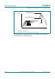
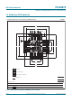
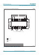
• Added Section 18 “Soldering: PCB footprints”
PCA9670 v.2 20070717 Product data sheet - PCA9670 v.1
PCA9670 v.1 20060620 Objective data sheet - -
Table 13. Revision history
…continued
Document ID Release date Data sheet status Change notice Supersedes